


25
NOTE: DIAGRAMS & ILLUSTRATIONS ARE NOT TO SCALE.
LENNOX HEARTH PRODUCTS • MERIT
®
PLUS DIRECT VENT GAS FIREPLACES (MPD33/35/40/45) • INSTALLATION INSTRUCTIONS
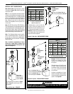
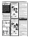
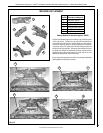
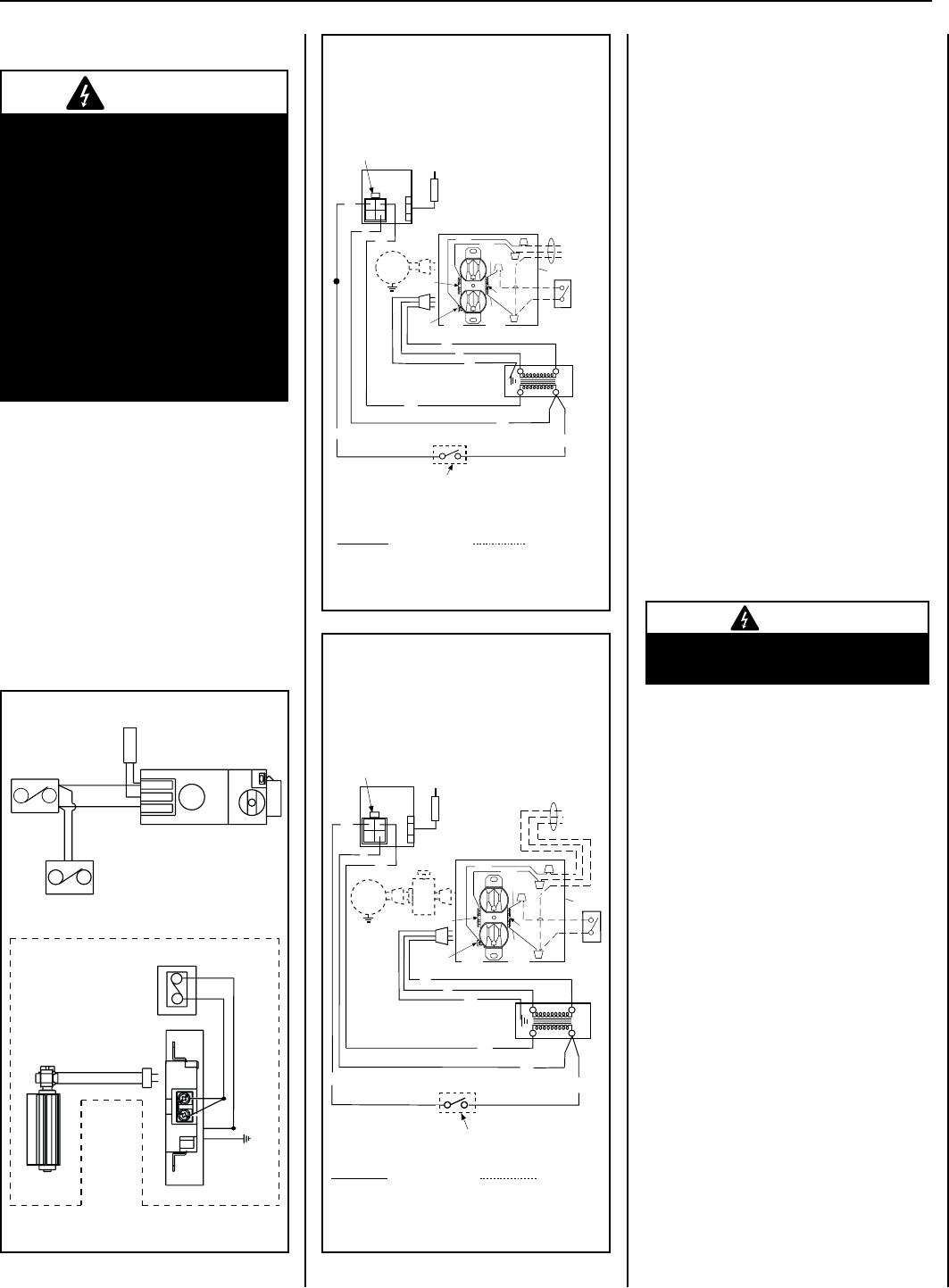
Step 5. FIELD WIRING
TP-TH
TP
TH
APPLIANCE- MOUNTED
ON/OFF SWITCH
(OPTIONAL)
BK/W(1)
BK/W(1)
WALL-MOUNTED ON/OFF SWITCH (OPTIONAL)
THERMOSTAT (OPTIONAL)
JUNCTION BOX
BLACK
W
GR
120 V
AC
WALL MOUNTED CONFIGURATION FOR FAN SWITCH (OPTIONAL)
BK
R
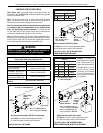
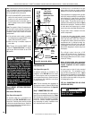
WIRING DIAGRAM MILLIVOLT GAS VALVES
THERMOPILE
GAS VALVE
FAN
(OPTIONAL)
Figure 47
CAUTION
The ground supply lead must be
connected to the wire attached to the
green ground screw located on the
outlet box (see wiring diagrams).
Failure to do so will result in a
potential safety hazard. The appli-
ance must be electrically grounded
in accordance with local codes or,
in the absence of local codes, the
National Electrical Code, ANSI/
NFPA 70-latest edition (in Canada,
the current CSA C22-1 Canadian
Electrical Code).
CAUTION: Label all wires prior to discon-
nection when servicing controls. Wiring
errors can cause improper and dangerous
operation.
ATTENTION: Au moment de l’entretien
des commandes, étiquetez tous les fils
avant de les débrancher. Des erreurs
de cáblage peuvent entraîner un fonc-
tionnement inadéquat et dangereux.
Verify proper operation after servicing.
S’assurer que l’appareil fonctionne adé-
quatement une fois l'entretien terminé.
1. If any of the original wire as supplied must be replaced,
1. it must be replaced with Type AWM 105°C – 18 GA. wire.
2. 120V, 60Hz – Less than 3 amps.
BK
Transf.
120 V.
24 V
Factory Wired Field Wired
BL
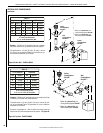
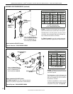
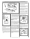
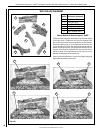
Electronic Wiring Diagram (Honeywell)
Showing the Blower Wiring for the Optional
FBK-250 Kits
R
WH
BL
W
Gas Valve
B
R
IGNITER
BK
Schematic Representation Only
*ON/OFF Switch (Integral
with Gas Valve)
Optional
FBK-250
Module
*Leave the ON/OFF switch, which is integral
with the gas valve, in the ON position.
G
OPTIONAL APPLIANCE-MOUNTED ON/OFF SWITCH
OR OPTIONAL WALL SWITCH OR OPTIONAL THERMOSTAT
OR OPTIONAL REMOTE RECEIVER
PILOT
ASSEMBLY
OPT
BLOWER
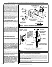
Junction Box
White
Green
Red
Black
Neutral
Side of
Receptacle
Tab Intact
Green
Ground
Screw
Hot
Side of
Receptacle
Tab
Broken
Optional
Accessory
Switch
120 VAC - Black
neerG-dnuorG
etihW-lar
t
ueN
1. If any of the original wire as supplied must be replaced,
1. it must be replaced with Type AWM 105°C – 18 GA. wire.
2. 120V, 60Hz – Less than 3 amps.
BK
Transf.
120 V.
24 V
Factory Wired Field Wired
BL
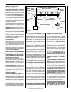
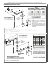
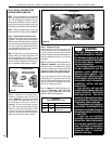
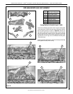
Electronic Wiring Diagram (Honeywell)
Showing the Blower Wiring for the Optional
FBK-100 and FBK-200 Kits
R
W
BL
W
Gas Valve
B
R
IGNITER
BK
*Blower speed control switch is provided in FBK200 blower kit.
Schematic Representation Only
**ON/OFF Switch (Integral
with Gas Valve)
**Leave the ON/OFF switch, which is integral
with the gas valve, in the ON position.
OPTIONAL APPLIANCE-MOUNTED ON/OFF SWITCH
OR OPTIONAL WALL SWITCH
OR OPTIONAL THERMOSTAT
OR OPTIONAL REMOTE RECEIVER
G
OPT
BLOWER
PILOT
ASSEMBLY
Junction Box
White
Green
Red
Black
Neutral
Side of
Receptacle
Tab Intact
Green
Ground
Screw
Hot
Side of
Receptacle
Tab
Broken
120 VAC - Black
neerG-dnuorG
Optional
Accessory
Switch
etihW-lar
t
ueN
Figure 49
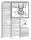
Figure 48
Refer to Section A for millivolt appliances and
Section B for electronic appliances. The gas
valve is set in place and pre-wired at the factory
on both models.
A. Millivolt Wiring (see Figure 47)
Millivolt units are not provided with any
factory-installed controls; therefore, one of the
optional control switches is required to operate
the unit (ON/OFF Wall Switch, Unit-Mountable
ON/OFF Switch*, Thermostat, Remote Control).
See the fireplace Care and Operation Instruc-
tions for details.
[*If using a Unit-Mountable ON/OFF Rocker Switch
with an optional Style View Door, mount the Rocker
Switch on the door instead of the unit.]
1. If installing an ON/OFF wall switch or ther-
mostat, mount it in a convenient location on
a wall near the fireplace.
2. Wire the control switch within the millivolt
control circuit using the 15 feet of 2 con-
ductor wire supplied with the unit.
Note: The supplied 15 feet of 2 conductor
wire has one end of each conductor con-
nected to the gas valve circuit and the other
end of each conductor placed loose inside
the bottom compartment.
CAUTION
In millivolt systems, do NOT connect
a Wall Switch to a 120V power supply.
B. Electronic Wiring
(see Figures 48 & 49)
The electronic gas valve has an integrated ON/
OFF burner control switch. One of the follow-
ing optional controls also may be used: ON/
OFF Wall Switch, Thermostat, Remote Control
(see fireplace Care and Operation Instructions
for details.).
Note: Electronic models must be connected to
the main power supply.
1. Route a 3-wire 120Vac 60Hz 1ph power
supply to the appliance junction box.
2. Remove the electrical inlet cover plate from
the side of the unit by removing the plate’s
securing screws (see Figure 13, Page 11).
3. Remove the cover plate knockout; then feed
the power supply wire through the knockout
opening and into the unit junction box.
4. See Figures 48 & 49. Connect the black
power supply wire to the lower outlet’s red
pigtail lead.
Connect the white power supply wire to the
outlet’s common terminal.
5. Connect the ground supply wire to the
pigtail lead attached to the outlet’s green
ground screw.