


9
NOTE: DIAGRAMS & ILLUSTRATIONS ARE NOT TO SCALE.
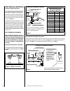
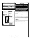
MINIMUM CLEARANCES* Inches (millimeters)
Sides 1/2 in. (13)
0 (0) from Spacers Or Dimples **
Top Spacers 0 (0)
Floor 0 (0)
From Bottom of Unit To Ceiling 72 (1829)
Vent 3 (76)
Top* / 1 (25.4) Sides & Bottom
SERVICE CLEARANCES Feet (meters)
Front, Back, Sides 3 feet (0.9 meters)
Table 5
WARNING
Failure to position the parts in accordance with these
diagrams or failure to use only parts specifically
approved with this appliance may result in property
damage or personal injury.
AVERTISSEMENT
Risque de dommages ou de blessures si les pièces
ne sont pas installées conformément à ces schémas
et ou si des pièces autres que celles spécifiquement
approuvées avec cet appareil sont utilisées.
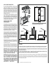
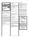
DETAILED INSTALLATION STEPS
The appliance is shipped with all gas controls and components installed
and pre-wired.
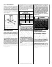
1. Remove the shipping carton. Remove the shipping pad, exposing
the front glass door.
2. Open the two latches (located under the firebox floor) securing the
glass door. Remove the door by tilting it outward at the bottom and
lifting it up. Set the door aside protecting it from inadvertent damage.
See Removing and Installing Glass Panels on Page 33.
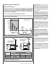
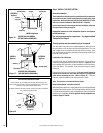
3. Remove the top louvered panel and locate the pressure relief plates
(see Figure 11).
4. Lift the pressure relief plates and remove the cardboard from beneath
each plate (be careful not to damage the white gasket).
1
(25)
2
(51)
3
(76)
1 (25)
2 (51)
3 (76)
4
(102)
4 (102)
5
(127)
5 (127)
6 (152)
7 (178)
8 (203)
9 (229)
10 (250)
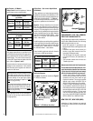
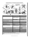
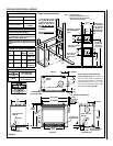
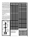
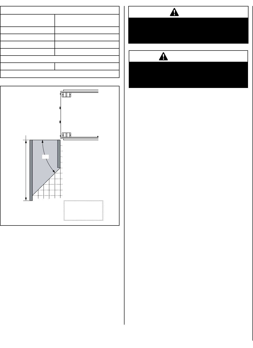
Combustible Materials
Allowed In Shaded Area
“Safe Zone”
Inches (millimeters)
Top View of
Fireplace
45
o
At 5" minimum side
wall clearance, the wall
(shown in dark gray) can
be any length.
Minimum
Distance to
Unprotected
Side Wall
One end of the unit may be
flush with a perpendicular
wall, but the wall at the other
end must not extend beyond
the front edge of the unit.
Figure 9