


10
NOTE: DIAGRAMS & ILLUSTRATIONS ARE NOT TO SCALE.
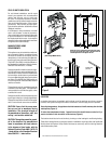
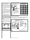
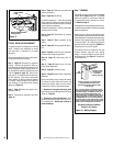
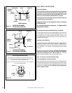
Unit Being Secured by Its Nailing
Flanges to the Framing
Note: The nailing flanges, combustible members
and screw heads located in areas directly adjacent
to the nailing flanges, are EXEMPT from the 1/2”
clearance to combustible requirements for the
firebox outer wrapper. Combustible framing may be
in direct contact with the nailing flanges and may
be located closer than 1/2” from screw heads and
the firebox wrapper in areas adjacent to the nailing
flanges. Frame the opening to the exact dimensions
specified in the framing details of this manual.
Side
Framing
Unit Nailing Flange
(No clearance to
combustible
framing is required)
Left Side Front Corner of Fireplace Shown
(Right Side Requirements the Same)
Unit Being Secured By Its Nailing Flanges
To The Framing
Figure 11
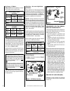
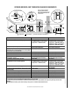
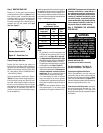
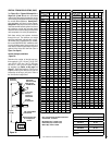
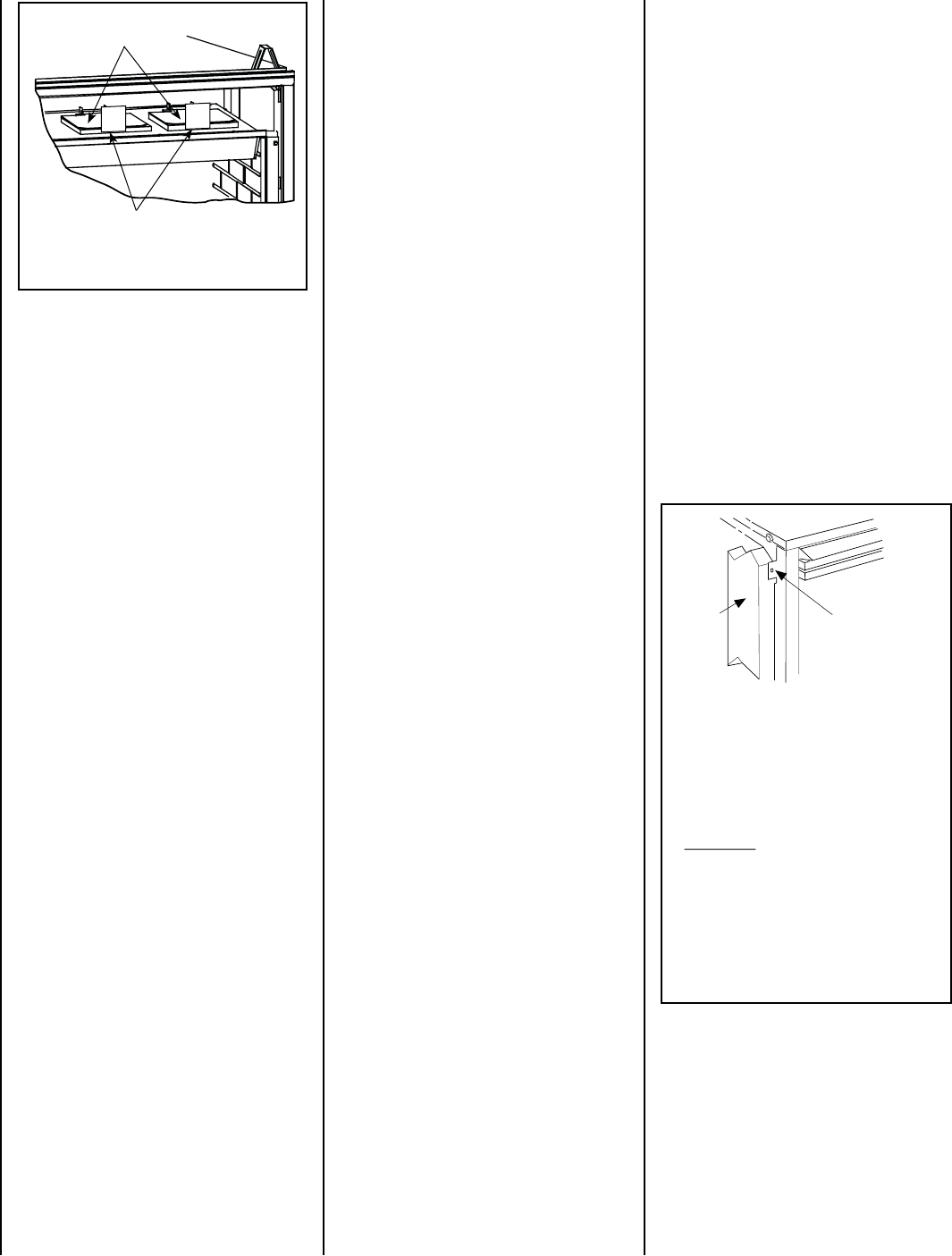
REMOVE
CARDBOARD
BEFORE USING
Pressure Relief
Plates
Remove Cardboard Before
Using Appliance
REMOVE
CARDBOARD
BEFORE USING
Figure 12 - Nailing Flanges
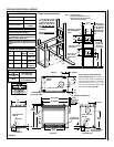
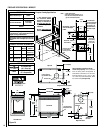
Step 1. FRAMING
Frame these appliances as illustrated in Figures
13 and 14 on Pages 11 and 12. All framing
details must allow for a minimum clearance
to combustible framing members as shown
in Table 5 on Page 8.
If the appliance is to be elevated above floor level,
a solid continuous platform must be constructed
below the appliance.
Headers may be in direct contact with the appli-
ance top spacers when they are bent up vertically
maintaining the 3" clearance to the fireplace top,
but must not be supported by them or notched
to fit around them. All construction above the
appliance must be self-supporting. DO NOT use
the appliance for structural support.
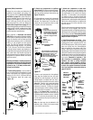
The fireplace should be secured to the side
framing members using the unit's nailing
flanges - one top and bottom on each side of
the fireplace front. See Figure 12. Use 8d nails
or their equivalent.
TYPICAL INSTALLATION SEQUENCE
The typical sequence of installation is outlined
below. However, each installation is unique
and may result in variations to the steps
described.
See the page numbers references in the follow-
ing steps for detailed procedures.
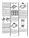
Step 1. (Page 10) Construct the appliance
framing. Position the appliance within the
framing and secure with nailing brackets. Bend
up the appropriate header spacing guides for
the drywall/finish material thickness to be used
(refer to Figure 62, page 33). Bend up the
outer pair for 1/2" materials and the inner pair
for 5/8" materials. Bend out the appropriate
nailing flanges for the drywall/finish material
to be used. Nailing flanges are provided for
flush framing, 1/2 inch and 5/8 inch framing
depths (see Figure 12).
Step 2. (Page 13) Route gas supply line to
appliance location.
Step 3. Preparing the appliance vent collar
(Page 13).
Step 4. (Page 14) Install the vent system and
exterior termination.
Step 5. (Page 26) Field Wiring
a. Millivolt Appliances – Install the operating
control switch (not factory provided) and bring
in electrical service line for forced air-circulating
blower (optional equipment).
b. Electronic Appliances – Field wire and install
operating control switch.
Step 6. (Page 27) Install blower kit (optional
equipment).
Step 7. (Page 27) Make connection to gas
supply.
Step 8. (Page 28) Verifying appliance opera-
tion.
Step 9. (Page 29) Install the logs, decorative
volcanic stone and glowing embers.
Step 10. (Page 33) Install glass door as-
sembly.
Step 11. (Page 33) Adjust burner to ensure
proper flame appearance.
Step 12. (Page 35) Install the hoods.
Step 13. (Page 36) Attach Safety in Operation
Warnings.
Before proceeding it may be helpful to remove
the log set form the firebox and remove the
embers and volcanic stone from the control
compartment. Refer to the following steps:
1. Remove the front glass enclosure panel
(see Removing and Installing Glass Enclosure
Panels on Page 33).
2. Remove log set box from firebox. Next,
remove embers and volcanic stone from con-
trol compartment. Handle logs carefully to
prevent breakage.