


41
NOTE: DIAGRAMS & ILLUSTRATIONS ARE NOT TO SCALE.
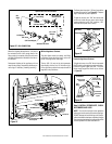
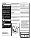
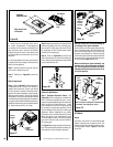
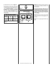
Pan Burner
Figure 72
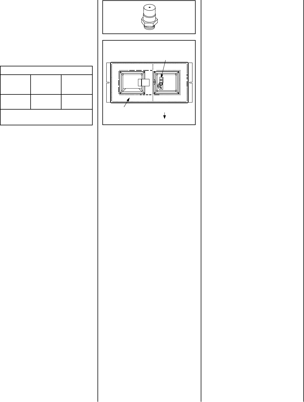
BURNER POSITIONING
Valve Access Side
Figure 71
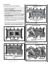
Step 9. Reassemble the remaining components
by reversing the procedures outlined in the
preceding steps.
Use pipe joint compound or Teflon tape on all
pipe fittings before installing (ensure propane
resistant compounds are used in propane ap-
plications, do not use pipe joint compounds
on flare fittings).
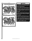
Step 10. Attach the conversion label provided
in the conversion kit to the rating plate on the
appliance.
Step 11. Turn on gas supply and test for gas
leaks.
b. Install the burner as shown in Figure 72.
Ensure that the arm of the venturi of the burner
is hooked onto the air shutter adjustment lever
(refer to Figure 66 on Page 40 ). The primary
air opening can be adjusted by rotating the
adjustment lever from beneath the firebox
floor. Refer to Figure 64 on Page 35 for the
recommended minimum primary air shutter
opening setting.
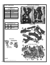
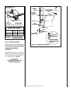
Pilot Assembly
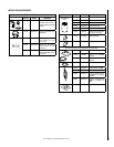
Burner Orifice Sizes (all models)
Elevation
Feet (meters)
Natural
Gas
drill size (inches)
Propane
Gas
drill size (inches)
0 - 4500
(0-1372)
#37 *
(.104")
1.55
mm *
(.061")
* Standard size installed at factory
Table 11