


15
NOTE: DIAGRAMS & ILLUSTRATIONS NOT TO SCALE.
Figure 28
Figure 29
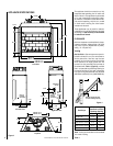
Step 9. Reassemble all removed components
by reversing the procedures outlined in the
preceding steps. Use pipe joint compound or
Teflon tape on all pipe fittings before installing
(ensure propane resistant compounds are used
in propane applications, do not use pipe joint
compounds on flare fittings).
Step 10. Attach the conversion label provided
in the conversion kit to the rating plate on the
appliance.
Step 11. Turn on gas supply and test for gas
leaks. (See
step 6
on page 8.)
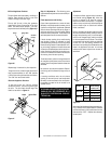
Figure 27
Step 5. Millivolt Systems – Attach manom-
eter to the manifold side pressure test fitting
and verify manifold pressure reads 3.5 inches
water column (0.87 kPa) for natural gas, and
10.0 inches water column (2.49 kPa) for pro-
pane gas.
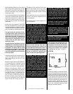
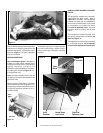
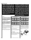
Step 6. See
Figure 26
and remove the pilot
hood assembly to access the hexed pilot ori-
fice. Remove and replace the orifice with the
one provided with the kit.
When reinstalling the ignitor assembly, use
extreme care to prevent damage and break-
age. Do not apply any leverage to the ignitor
assembly while restoring the retainer clip to
its original position.
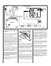
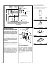
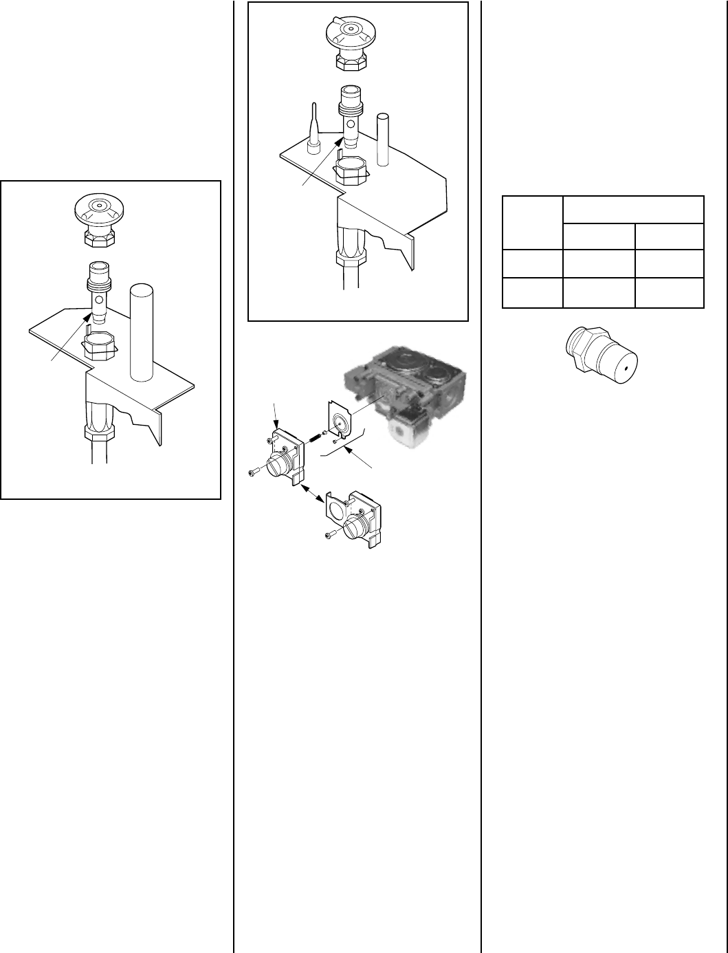
All Models
Step 8. Unscrew the orifice from the manifold
and replace it with the one provided with the
kit
.
See the following table for orifice sizes for
natural and propane models.
Figure 29
illus-
trates the orifice.
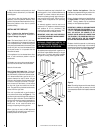
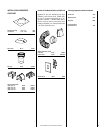
Refer to
Figure 27
and replace the pilot orifice
as follows: Remove the pilot hood assemble
to access the hexed polot ofifice.
Remove the pilot orifice and replace it with the
one provided with the conversion kit. Reinstall
the pilot assembly by reversing the steps de-
tailed here.
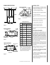
Figure 26
Pilot
Orifice
Pilot
Orifice
LSBV
Series
Natural
Propane
Orifice Size
3628 #26 #45
4228 #26 #45
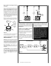
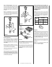
Electronic Appliances
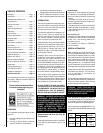
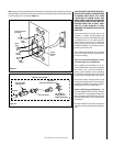
Step 7. SIT Electronic Valves - See
Figure 28
and the instructions provided with the kit.
Remove the slotted cap screw, o-ring, pres-
sure-regulating adjusting screw and spring,
then discard.
Modify the pressure regulator from the kit.
Using a standard tin snip cutting tool, proceed
to trim shoulder off of the regulator.
Install new components and modified pres-
sure regulator from the kit.
Attach manometer to the manifold side pres-
sure test fitting and adjust screw until pres-
sure reads 3.5 inches water column (0.87 kPa)
for natural gas, and 10.0 inches water column
(2.49 kPa) for propane gas.
Modified Kit
Pressure Regulator
- After Trim
Remove
These
Components
SIT VALVE
Kit Pressure
Regulator - Before
Trim