


5
NOTE: DIAGRAMS & ILLUSTRATIONS NOT TO SCALE.
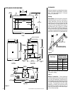
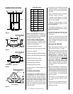
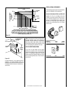
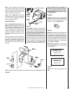
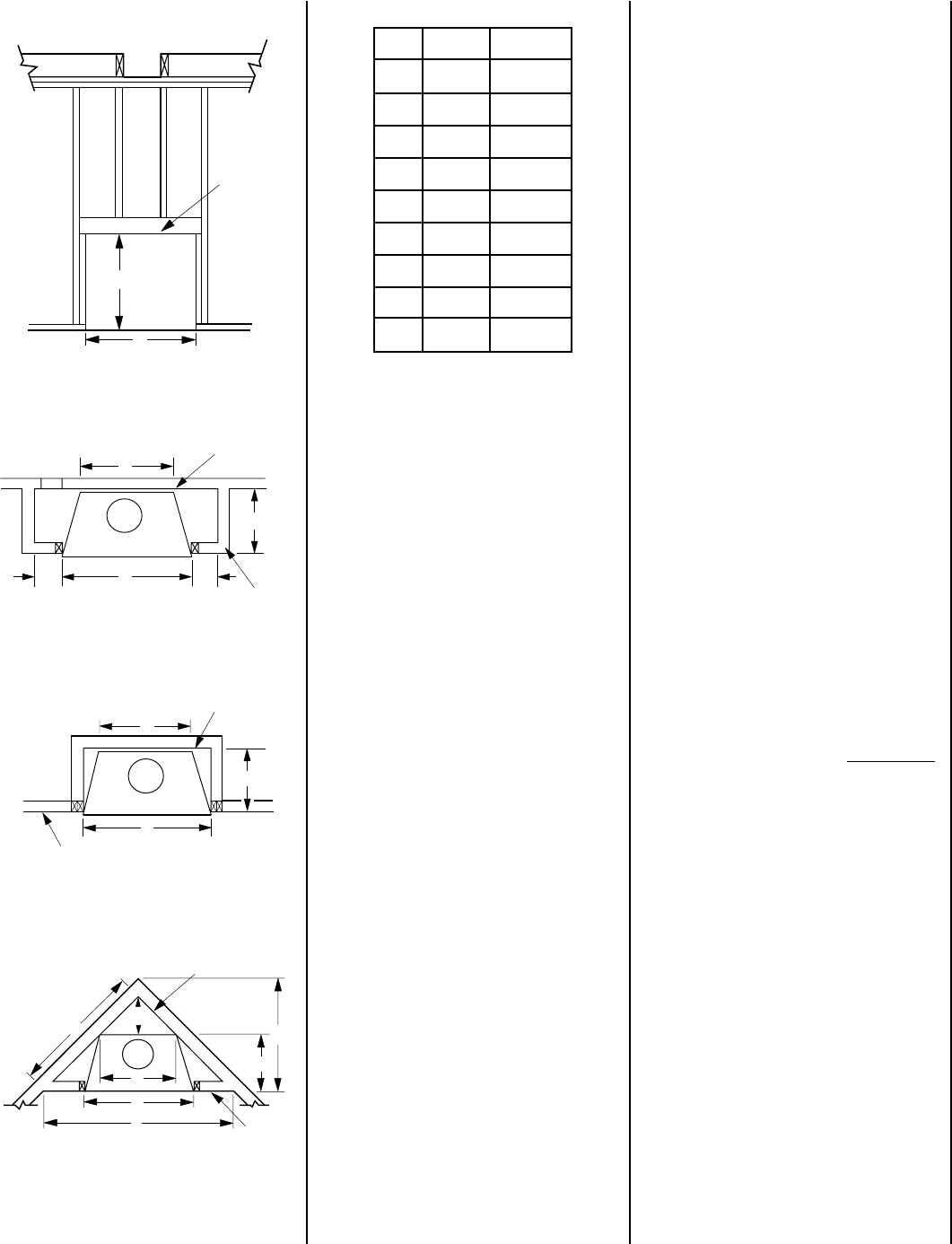
FRAMING SPECIFICATIONS
Figure 4
Figure 5
Figure 6
Framing Dimensions
Note: All framing dimensions calculated for 1/2"
dry wall at the appliance face. If sheathing the
chase or finishing with other thickness materials,
calculations will need to be made.
TYPICAL INSTALLATION SEQUENCE
The typical sequence of installation follows,
however, each installation is unique resulting in
variations to those described.
1. Construct the appliance framing.
2. Route gas supply line to appliance location.
3. Position the appliance.
4. Install the vent system and exterior termination.
5. Field wire and install operating control switch.
6. Make connection to gas supply.
7. Install (optional) outside Air Kit.
8. Install the logs and rockwool.
9. Checkout appliance operation.
10. Adjust burner to ensure proper flame
appearance.
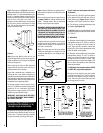
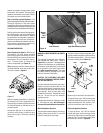
PRE-INSTALLATION NOTES
The fireplace may be installed directly on a
combustible floor or raised on a platform of an
appropriate height. Do not place fireplace on
carpeting, vinyl or other soft floor coverings. It
may, however, be placed on flat wood, plywood,
particle board or other hard surfaces. Be sure
fireplace rests on a solid continuous floor or
platform with appropriate framing for support
and so that no cold air can enter the room from
under the fireplace.
* When FOAK is used.
The fireplace may be positioned and then the
framing built around it, or the framing may be
constructed and the fireplace positioned into
the opening.
Usually, no special floor support is needed for
the fireplace, however, to be certain:
1. Estimate the total weight of the fireplace
system and surround materials such as brick,
stone, etc., to be installed.
2. Measure the square footage of the floor
space to be occupied by the system, surrounds
and hearth extensions.
3. Note the floor construction, i.e. 2 x 6’s, 2 x
8’s or 2 x 10’s, single or double joists, type and
thickness of floor boards.
4. Use this information and consult your local
building code to determine if you need addi-
tional support.
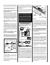
If you plan to raise the fireplace and hearth
extension, build the platform assembly then
position fireplace and hearth extension on top.
Secure the platform to the floor to prevent
possible shifting.
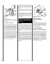
INSTALLING THE FIREPLACE
Step 1. Frame appliance enclosure as illus-
trated in
Figures 4 through 7
on page 5.
Note: The nailing flanges, combustible fram-
ing members and screw heads located in areas
directly adjacent to the nailing flanges, are
EXEMPT from the
¹⁄₂
" clearance to combus-
tible requirements for the firebox wrapper.
Combustible framing may be in direct contact
with the nailing flanges and may be located
closer than
¹⁄₂
" from screw heads and the
firebox wrapper in areas adjacent to the nailing
flanges. Frame the opening to the exact di-
mensions specified in the framing details of
this manual.
Note: The framed depth, 21
⁵⁄₈
" (549 mm) from
a framed wall, must always be measured from
a finished surface. If a wall covering such as
drywall is to be attached to the rear wall, then
the 21
⁵⁄₈
" (549 mm) must be measured from
the drywall surface. It is important that this
dimension be exact.
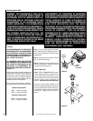
If the appliance is to be elevated above floor
level, a solid continuous platform must be
constructed.
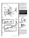
The header may rest on the top metal spacers,
but must not be notched to fit around them.
Consult all local codes.
Figure 7
Header
B
A
Fireplace Framing
C
A
G
Inside Chase
HH
Back Wall of Chase/Enclosure
Including Finising Materials
if any
Rough
Framing Face
(Unfinished Shown)
A
Outside Chase
G
C
Back Wall of Chase/Enclosure
Including Finising Materials
if any
Rough
Framing Face
(Unfinished Shown)
Corner Installation
J
D
C
A
E
G
F
Back Wall of Chase/Enclosure
Including Finising Materials
if any
Rough
Framing Face
(Unfinished Shown)
A 46 ¹⁄₄" 1175 mm
B 43 ¹⁄₂" 1105 mm
C 33" 838 mm
D 17 ¹⁄₂" 445 mm
E 76 ¹⁄₄" 1937 mm
F 38 ¹⁄₈" 968 mm
G 21 ⁵⁄₈" 549 mm
H* 8" 203 mm
J 20 ⁵⁄₈" 524 mm
K 53 ⁷⁄₈" 1368 mm