


Outside Air Installation
The outside air assembly may be installed according to the following
requirements:
A) Duct length should be kept to a minimum. The maximum length of a
4” interior diameter (100 mm) insulated flexible duct is twenty (20)
feet (6.1 m). (See note below).
B) The air intake register must not be installed more than ten (10) feet
(3050 mm) above the base of the fireplace.
C) The fresh air must come from outside the house. The air intake must
not draw air from the attic, basement or garage.
D) The air intake should be installed where it is not likely to be blocked by
snow or exposed to extreme wind and away from automobile exhaust
fumes, gas meters and other vents.
E) The duct and register may be installed above or below floor level.
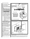
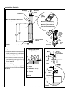
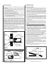
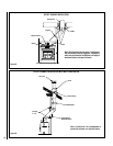
Make a 4-1/4” (110 mm) hole in the outside wall of the house at the chosen
location. From outside, place the outside air register in the hole (open
side down) and fasten the register to the wall with screws as shown (see
Figure 20
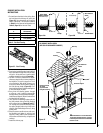
). Slip the pipe into the insulated sleeve. Place the insulated
pipe over the register tube and over the fireplace’s outside air connector
(see Figure 21). At each end, carefully pull back the insulation and plastic
cover exposing the flexible pipe. Using the aluminium tape provided,
wrap the tape around the joint between the flexible pipe and the air inlets.
Carefully push the insulation and plastic cover back over the pipe. Using
aluminium tape, fasten the plastic cover in place.
NOTE: We recommend not to exceed twenty (20) feet of 4” flexible pipe.
If you require a longer length we recommend that you use a 5” diameter
flexible pipe for the complete run up to thirty (30) feet and a 6” diameter
pipe for a run of up to forty (40) feet.
Figure 20
OUTSIDE CONNECTION
Figure 21
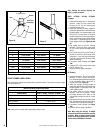
Figure 22
Aluminum Tape
Aluminum Tape
Fireplace
Connection
Plastic
Cover
Insulation
Flexible Pipe
Fireplace
OUTSIDE AIR CONNECTION
TO THE FIREPLACE
THE CHIMNEY SYSTEM
Chimney Installation Notes
1. If possible, install an interior chimney as it will provide better perfor
-
mance. In areas with continuous temperatures below -18° C (0° F),
the use of an exterior chimney increases the likelihood of operating
problems such as low draft, high rate of creosoting, and poor start-up
characteristics. Exterior chimneys are also prone to down-draft and
flow reversal. Installations, which are located on lower floors in the
house, such as in a basement, in combination with outside chimney,
are especially prone to flow reversal.
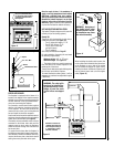
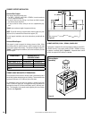
2. The Lennox Hearth Products fireplace model Ladera may be installed
only with Security Chimneys International 6” diameter chimney sys-
tems. The Ladera fireplace may also be installed with a 7’’ chimney
system (ASHT or HT6103) using the optional 6AW7 7’’ adaptor (7’’
AC chimney is not allowed). For more information refer to chimney
installation manual.
3. A chimney venting a fireplace shall not vent any other appliance.
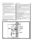
4. The minimum chimney height is twelve (12) feet (3.7 m). In altitude,
add 18” (450 mm) to the chimney for every 2,000 feet (600 m) above
sea level.
5.
All chimney installations must include at least one support. Re-
ducing the amount of chimney weight on the fireplace will help avoid
the noise created when the fireplace expands. This can be achieved
by having the chimney supported by the supports. The maximum
chimney length that can be supported by the fireplace is nine (9) feet
(2.75 m) for S-2100+/HT6000+, twelve (12) feet (3.7 m) for ASHT+
/ HT6103+ and 26 feet (8 m) for AC chimney.
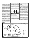
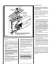
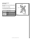
6. The chimney must extend at least three (3) feet (915 mm) above its point
of contact with the roof and at least two (2) feet (610 mm) higher than
any wall, roof or building within ten (10) feet (3m) of it (Figure 22).
7. If the chimney extends higher than five (5) feet (1,500 mm) above its point
of contact with the roof, it must be secured using a roof brace.
8. A rain cap must be installed on top of the chimney. Failure to install
a rain cap may cause corrosion problems.
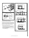
9. Cut and frame square holes in all floors, ceilings, and roof that the
chimney will go through to provide a 2” (50 mm) clearance between
the chimney and any combustible materials. Do not fill this 2” space
with insulation or any other combustible material.
10. Portions of the chimney which may extend through accessible spaces
must be enclosed to avoid contact with combustible materials or
damage to the chimney.
11.When offsets are used, the pipe may not penetrate a ceiling or floor
unless it is running vertical (no 30° offsets).
Outside
Intake
Screw
Opening
Facing
Down
Wall
Aluminum Tape
Plastic Cover
Insulation
Flexible Pipe
Aluminum Tape
ten (10) feet
three (3) feet Min.
two (2) feet Min.
14
NOTE: DIAGRAMS & ILLUSTRATIONS ARE NOT TO SCALE.