


NOTE: DIAGRAMS & ILLUSTRATIONS ARE NOT TO SCALE.
15
LENNOX HEARTH PRODUCTS • ESTATE™ SERIES WOOD-BURNING FIREPLACES • MODELS EST-36, EST-42, EST-50 • INSTALLATION INSTRUCTIONS
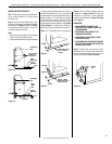
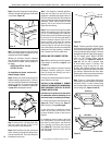
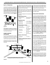
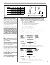
MULTIPLE TERMINATIONS
If more than one termination is located in the
same chase or within the same general prox-
imity, we suggest they should be separated
in distance at least 24" (610 mm) horizontally
from flue center to flue center and stacked or
staggered vertically at least 18" (457 mm) apart,
from the termination of one smoke exit to the
termination of another smoke exit (Figure 34).
18"
(457mm)
18"
(457mm)
24"
(610mm)
Figure 34
This suggestion is provided in the interest of
better operation. If the terminations are located
too close to each other, smoke may migrate
from one flue into the other.
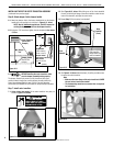
CHIMNEY COMPONENT
CALCULATIONS
The minimum installed height of the completed
replace system is 16'0" (4.8 m) for 36" and
42" models and 17'6" for 50" models. The
maximum system height is 80'0" (24.38 m).
To determine the number of chimney sections
and chimney components required, follow
these steps:
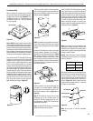
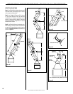
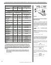
Figure 35
3' Min.
(916mm)
Less Than 10' (3m)
2' Min. (610mm) 2' Min. (610mm)
2' Min.
(610mm)
CTDTM
Shown
Note: Both CTD and CTDTM terminations shown for illustration purposes.
Use appropriate termination for the fireplace model installed.
1. Determine total vertical height of the fireplace
installation. This dimension is the distance from
the surface the fireplace sets on to the point where
smoke exits from the termination.
2. Determine the number of chimney compo-
nents required, except chimney sections. This
would include firestop spacers, stabilizers, roof
flashing, etc.
3. The effective heights of the components are
listed below.
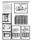
Fireplace Effective Heights
EST-36 & EST-42 = 65-1/4" (1657 mm)
EST-50 = 84" (2134 mm)
Pipe Effective Heights
FTF10/13-12 = 10-1/4" (260 mm)
FTF10/13-18 = 16-1/4" (413 mm)
FTF10/13-36 = 34-1/4" (870 mm)
Termination Effective Heights
FTF10-CTDTM = 10" (254 mm)
FTF10/FTF13-CT2 = 15" - 23"
(381 - 584 mm)
FTF13-CTD = 4" (102 mm)
FTF13-CTDT = 12" - 18"
(305 - 457 mm)
FTF13-CT1 = 12" - 18"
(305 - 457 mm)
Stabilizer* Effective Heights
S4 Stabilizer = 3" (76 mm)
__________
*Stabilizer is required for every 30' (9.1 m)
of vertical chimney and/or 10' (3.03 m) of
offset chimney.
4. Determine amount of chimney height required
by subtracting total combined height of all pre-
selected components (fireplace and chimney
components from total desired height.)
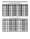
Reference Vertical Elevation Chart and deter-
mine the number of chimney sections (quantity
and length) required.
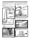
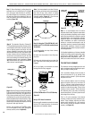
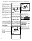
SPECIAL OFFSET INSTRUCTIONS
To clear any overhead obstructions, you may
offset your chimney system using Security's 30°
offset and return elbows. Use two elbows - an
offset elbow to initiate the offset and a return
elbow to terminate it. A 30° offset elbow, angling
in any direction, may be the first component used
off the top of the fireplace flue collar.
The offset and return elbows may be attached
together, or a section or sections of chimney
may be used between, but must not exceed 20'
(6.1 m) in total length between elbows (Figure
36). If sections of pipe exceed 10' (3 m) between
elbows, a chimney stabilizer must be used at the
midpoint. The stabilizer support straps must be
attached under tension (in shear) to structural
framing members above. When two sets of
elbows are used, the maximum combined length
of chimney used between elbows cannot exceed
20' (6.1 m) (Figure 37). Example: If C
1
= 10' (3
m) then C
2
cannot exceed 10' (3 m).
If an offset exceeds 6' (1.8 m) in length, each
chimney joint beyond the rst 6' (1.8 m) of
offset to the return elbow, must be secured by
a No. 8 x 1/2" sheet metal screw located at the
underside of the joint (Figure 38).
A 1/8" (13 mm) diameter hole must be drilled
in the chimney joint using a 1/8" (13 mm)
diameter drill. Hole should be drilled in center
of joint overlap (Figure 39). Be sure to drill
only through the outer chimney casting. Do
not puncture the inner flue.
Maximum offset of chimney system is 30°. Two
offsets must not be assembled to form a 60°
offset. However, two sets of offset and return
elbows may be used on a single flue system,
provided the total height of the system exceeds
22' (6.7 m) (Figure 42).
Return elbow support straps must be securely
attached under tension (in shear) to structural
framing members above. Do not substitute a
FTF10-30 or FTF13-30 offset elbow in place
of a FTF10-E30 or FTF13-ES30 return elbow.