


NOTE: DIAGRAMS & ILLUSTRATIONS ARE NOT TO SCALE.
5
LENNOX HEARTH PRODUCTS • ESTATE™ SERIES WOOD-BURNING FIREPLACES • MODELS EST-36, EST-42, EST-50 • INSTALLATION INSTRUCTIONS
CAUTION: DO NOT BLOCK THE HEAT-CIR-
CULATING AIR INLET AND OUTLET PORTS
ON CIRCULATING MODELS. DOING SO MAY
RESULT IN A POTENTIAL FIRE HAZARD.
If you plan to raise the fireplace and hearth
extension, build the platform assembly, then
position replace and hearth extension on
top. Secure the platform to the floor to prevent
possible shifting.
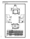
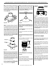
CLEARANCES
Minimum clearance to combustibles for the
Estate fireplace is as follows; sides and back –
1" (25.4 mm), combustible floor – 0" (0 mm),
adjacent wall 18" (457 mm), adjacent shielded
wall (K factor of .84 or less 24" W x 36" H) 12"
(305 mm), ceiling – 37-1/2" (953 mm).
Note: Clearance at the nailing flange for both
fireplace models is 0" (0mm).
Note: Adjacent wall considerations are for
an adjacent wall on only a single side. Walls
should not be placed at minimum distance at
both sides of the fireplace.
ASSEMBLY STEPS
Note: The following steps represent the normal
sequence of installation. Each installation is
unique, however, and may require a different
sequence.
1. Position rebox prior to framing or into
prepared framing.
2. Install Cold Climate Kit (Canada only).
3. Install the chimney system.
4. Install optional outside combustion air kit.
5. Plumb gas line if a decorative gas appliance
will be used. (Gas connections should only be
performed by an experienced, licensed/certied
tradesman.)
6. Complete the installation; finish wall mate-
rial, surround and hearth extension to your
individual taste.
7. Assemble and attach optional glass door
assembly.
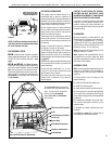
See Figure 1 on page 3 for a general idea of
each element of the fireplace system.
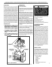
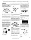
Figure 5
PRE-INSTALLATION NOTES
The fireplace may be installed directly on a
combustible floor or raised on a platform of
an appropriate height. Do not place fireplace on
carpeting, vinyl or other soft floor coverings. It
may, however, be placed on flat wood, plywood,
particle board or other hard surfaces.
Be sure replace rests on a solid continuous
floor or platform with appropriate framing for
support and so that no cold air can enter the
room from under the fireplace.
The fireplace may be positioned and then the
framing built around it, or the framing may be
constructed and the fireplace positioned into
the opening.
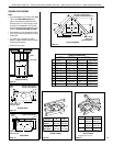
Usually, no special floor support is needed for
the fireplace, however, to be certain:
1. Estimate the total weight of the fireplace
system including chimney and surround ma-
terials such as brick, stone, etc., to be installed.
Shipping weights for the fireplace may be found
on page 23.
2. Measure the square footage of the floor space
to be occupied by the system, surrounds and
hearth extensions.
3. Note the oor construction, i.e., 2 x 6’s,
2 x 8’s or 2 x 10’s, single or double joists, type
and thickness of floor boards.
4. Use this information and consult your local
building code to determine if you need ad-
ditional support.
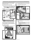
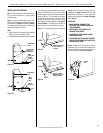
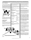
Wall
Covering
Black Portion Of Frame
Not To Be Covered With
Combustible Materials
Safe
Zone
15°
4-3/4”
18”
Door
Opening
1/2”
NOTE: Do NOT permanently place furniture or
other items such as decorative pillows within
60" of the fireplace front face.
PRE-ASSEMBLY STEPS
EST-50: Install the outer transition assembly
before installing the fireplace. See “Installating
the EST-50 Outer Transition Assembly” (next
page).
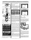
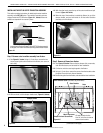
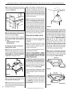
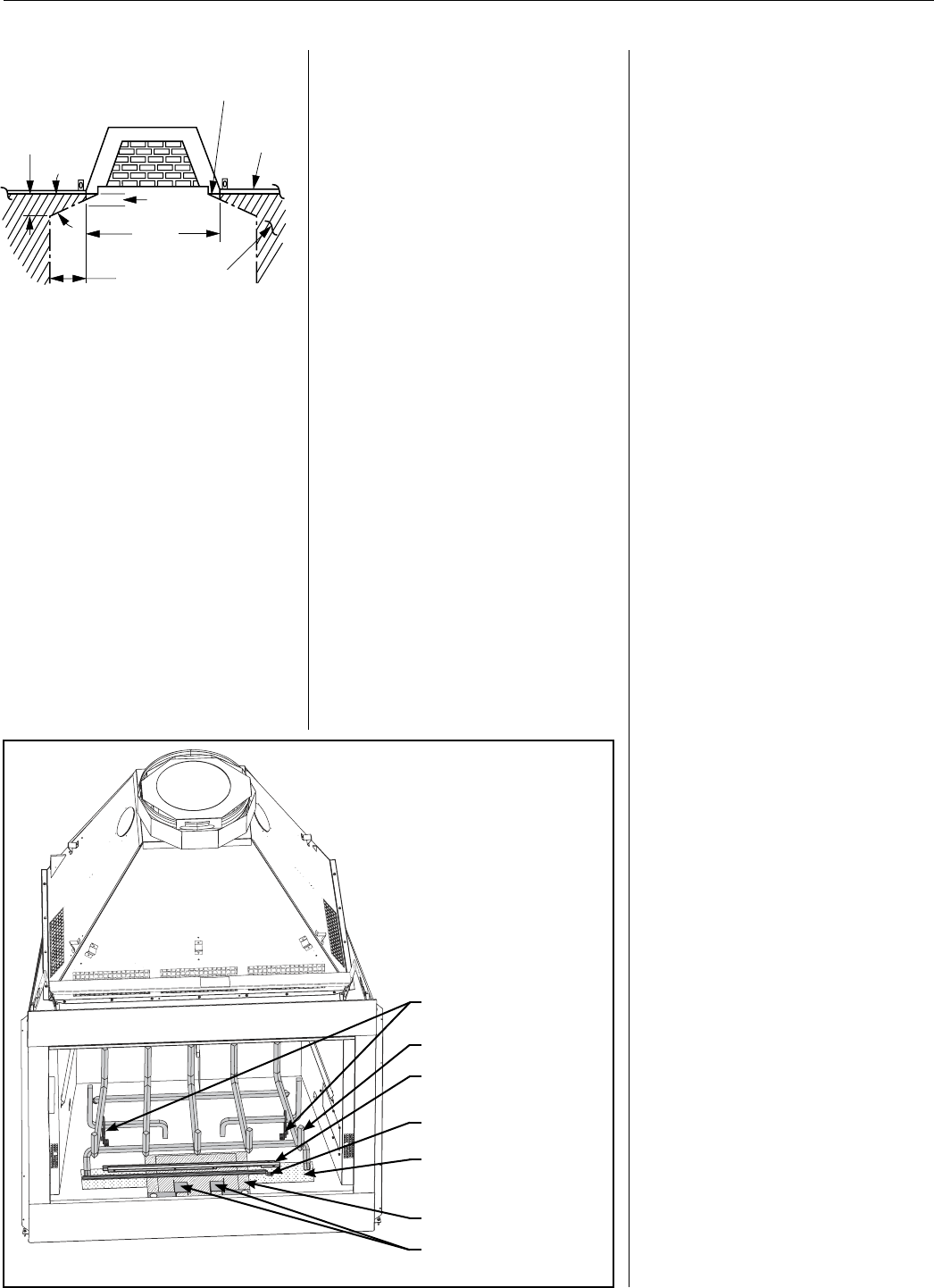
EST-36 and EST-42: See Figure 6, below.
Remove all items packed under the grate and
set aside for later installation. Cut the two wire
ties securing the grate, and discard the ties.
Remove the grate, and set aside for later instal-
lation. Using a 1/4" nut driver, remove the two
tie brackets from the rebox oor, and discard
the tie brackets.
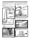
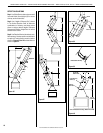
Figure 6: EST-36 and EST-42 Assembly
Screen Rods
Wire (Mesh) Firescreens
Grate Brackets
Grate
Cut the wire ties holding the grate to
the firebox floor, and remove the grate.
Use a 1/4" nut driver to remove the
screws from the tie brackets.
Discard wire ties and tie brackets
after removal.
Literature and Hardware
Front Refractory Retainers
(EST-42 only)
Wire Ties and Tie Brackets