


NOTE: DIAGRAMS & ILLUSTRATIONS ARE NOT TO SCALE.
14
LENNOX HEARTH PRODUCTS • ESTATE™ SERIES WOOD-BURNING FIREPLACES • MODELS EST-36, EST-42, EST-50 • INSTALLATION INSTRUCTIONS
Locking Band
Waterproof
Caulk
Roof Ridge
120°
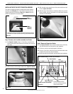
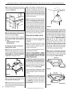
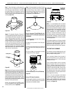
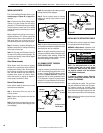
Step 8. The standard Security Chimneys™
FTF10 roof ashing assemblies include a storm
collar. Slide the storm collar over outer chimney,
rest on flashing spacers and align with top
surface of flashing. Insert tab in slot, pull tight
and bend tab back over slot. Seal storm collar
to outer chimney with roof caulking or mastic
around entire circumference of pipe. Also add
extra roof caulking to the tab/slot area to seal
completely against water penetration (Figure
30). Check all joints very carefully to ensure no
water intrusion can take place.
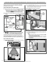
Figure 31
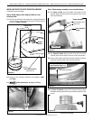
Figure 29
Step 7. Secure flashing by nailing along the
perimeter into roof using 8d nails. If shingled
roof, slide upper end and sides of roof flash-
ing under shingles (trim if necessary), seal the
top and both sides of the flashing to the roof
with roof caulking. Cover nail heads with roof
caulking (Figure 29).
Figure 30
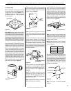
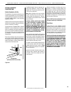
Step 9. Security Chimneys locking bands, Model
FLB, may be required if the chimney extends too
high above the roof flashing. As a general rule,
if the chimney extends more than 6' above the
roof flashing, the use of locking bands is advis-
able to strengthen the chimney assembly. Align
the locking band at the chimney joint. Locking
bands wrap around pipe joints equally covering
the joints of both pipe sections.
Use the nut provided and TIGHTEN snugly.
Do not overtighten as this might damage the
chimney section (refer to Figure 30).
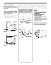
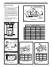
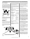
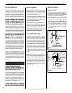
Step 10. Using the FTF10-CTDTM (36" & 42"
models) and FTF13-CTD (50" models) Round
Termination:
1. Hold termination over top of last chimney
section (Figure 32).
2. Center inner slip section in inner flue pipe-
slip down.
3. Center outer locking section over outer flue
pipe. Push down until locking tabs are firmly
engaged.
4. Pull up slightly on termination to ensure
locking joint has firmly engaged.
Figure 33
Note: It is recommended that all exterior
exposed related metal fireplace components;
such as terminations, flashings, storm collars
and/or flue be painted with a premium-quality,
high-temperature, rust-preventative paint de-
signed for metal. This is especially important
when installations are made in abnormally
adverse or corrosive environments; such as
near lakes, oceans or in areas with consistently
high-humidity conditions. Consult the paint
manufacturers instructions for proper prepara-
tion and application.
For Canadian installations, all chimney installed
outside the building must be galvalume (outer
sections only), effective January 1, 1992. The
appropriate model designations (with a “C”
sufx) are located in the back of this manual.
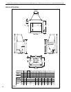
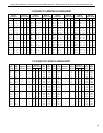
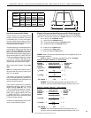
TEN-FOOT RULE SUMMARY
The minimum chimney height above the roof
and/or to adjacent walls and buildings is speci-
fied by all major building codes.
If the horizontal distance from the peak of
the roof is less then 10' (3 m), the top of the
chimney must be at least 2' (610 mm) above
the peak of the roof.
If the horizontal distance from the chimney
edge to the peak of the roof is more than 10'
(3 m), a chimney height reference point is
established on the roof surface 10' (3 m) hori-
zontally from the chimney edge. The top of the
chimney must be at least 2' (610 mm) above
this reference point. In all cases, the chimney
cannot be less than 3' (914 mm) above the roof
at the edge of the chimney.
The 2' in 10' rule is necessary in the interest
of safety, but does not ensure smoke-free op-
eration. Trees, buildings, adjoining roof lines,
adverse wind conditions, etc., may require a
taller chimney should the fireplace not draft
properly (see Figure 35).
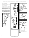
FTF10-CT2RS
Termination
2" (51mm) Min.
Air Space to
Combustibles
Studs
Above
Roof
20"
(508mm)
Note: If chimney extends more than 8' above
roof surface, guy wires are also recommended.
Use three (3) guy wires, attach to locking
band assembly, extend and secure to roof in a
triangular pattern (Figure 31). Guy wires are
not supplied by the manufacturer.
Figure 32
Using a CT2 Chase Termination
Refer to specific installation instruction included
with the CT2 chase termination for clearance
statements and installation details.
(FTF10-CTDTM shown FTF13-CTD Similar)