


NOTE: DIAGRAMS & ILLUSTRATIONS ARE NOT TO SCALE.
18
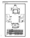
LENNOX HEARTH PRODUCTS • ESTATE™ SERIES WOOD-BURNING FIREPLACES • MODELS EST-36, EST-42, EST-50 • INSTALLATION INSTRUCTIONS
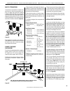
Return
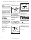
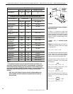
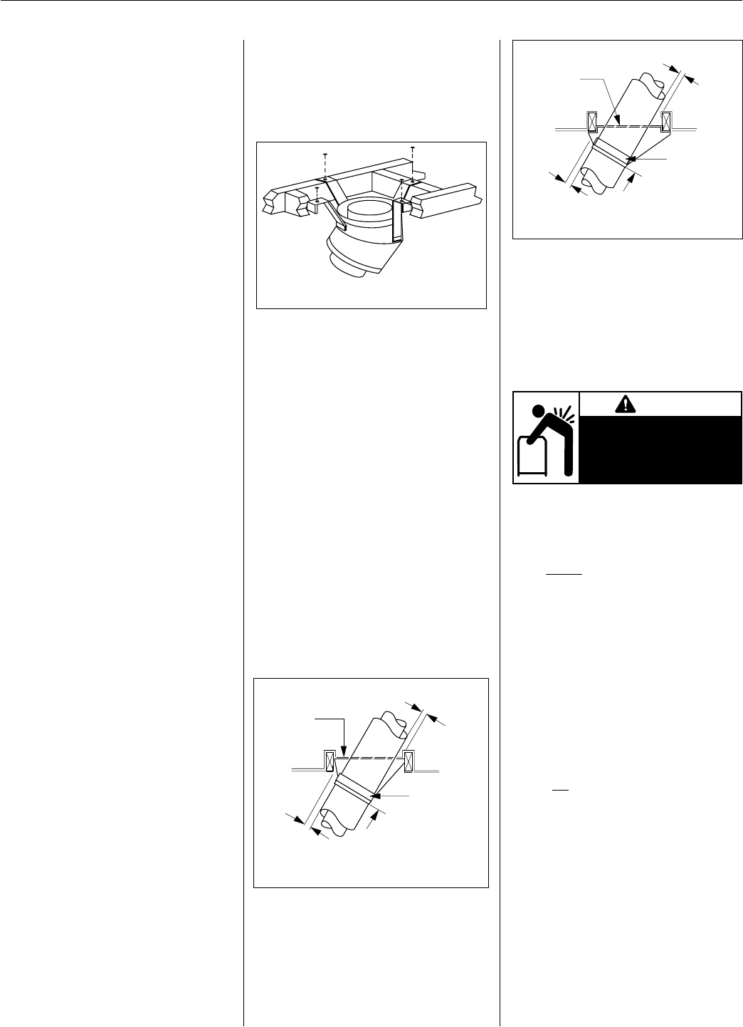
Elbow
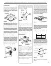
Figure 41
Note: The return elbow assembly performs the
same function as a stabilizer. Consider this when
determining the need for a stabilizer.
Note: Do not apply excessive pressure to any
subsequent chimney section following return
elbow assembly when installing. Ensure that
each subsequent chimney section is securely
attached by testing as noted above.
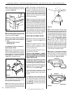
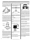
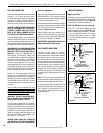
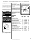
30° CHIMNEY OFFSET THROUGH
FLOOR OR CEILING
It may be necessary to assemble the chimney
at 30° when passing through the oor or ceil-
ing area. Use the F10FS30-2 restop spacer
as shown in Figures 42 and 43. Support the
chimney at floor or ceiling penetration with a
FTF10 stabilizer if distance of chimney below
ceiling is 10' or more. Maintain 2" minimum air
space to combustibles from chimney sections.
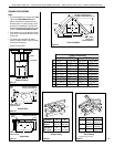
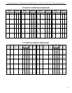
INSTALLING OFFSETS
First, review the Offset Elevation Chart on the
previous page and Figure 40 on page 16 for
reference.
Step 1. Determine the offset distance where
chimney is to pass through the first ceiling-
dimension “A.” To find this point on your ceiling,
first determine the center point for a vertical
chimney following the instructions for vertical
installation.
Measure height to the ceiling from the top of
replace-dimension “B.” Use the appropriate
Offset Elevation Chart to find dimension “A.”
Mark point where you will drive your nail to
show the center point for your offset ceiling cut.
Step 2. Proceed by using the Straight Up In-
stallation Instructions for cutting and framing
ceiling and roof openings.
Note: See Framing and Dimension Chart for
the sizes of the ceiling and roof openings. The
size of the roof opening varies with the degree
of pitch of the roof.
Offset Elbow Assembly
Offset elbows install the same as chimney
sections. First, snap the inner section INTO the
preceding inner section of flue. Check connec-
tion by pulling up slightly to ensure a tight fit.
Next, the outer sections snap lock OVER the
preceding outer section of chimney. Again,
check outer section by pulling up slightly to
ensure proper connection is made.
Return Elbow Assembly
Return elbows install the same way as round
terminations and stabilizers:
Step 1. Hold return elbow over top of last
chimney section.
Step 2. Center inner slip section into inner flue
pipe-slip down.
Step 3. Center outer-locking section over outer
chimney pipe. Push down until locking joint has
firmly engaged.
F10FS30-2
Firestop Spacer
FTF10-S4
Stabilizer
2" Min.
Air Space
30 Degree Firestop
And Attic Above
10’
Max.
Attic Space
2" Min.
Air Space
F10FS30-2
Firestop Spacer
FTF10-S4
Stabilizer
30 Degree Firestop
And Room Above
10’
Max.
Room Above
2" Min.
Air Space
2" Min.
Air Space
Figure 43
Figure 42
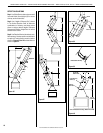
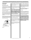
INSTALLING THE REFRACTORY PANELS
All Estate Series refractory panels are shipped
in a separate pallet from the fireplace.
WARNING: Lifting Hazard. Installation of the
refractory panels requires at least two people.
Step 4. Pull up slightly on return elbow to ensure
locking joint has firmly engaged.
Step 5. Secure support straps to framing
members by nailing under tension in sheer
(Figure 41).
NOTE: The side panels have a gas line
knockout located near the center bottom
of each panel. Make sure the side panels
are properly oriented, with the knockout
at the bottom of each panel.
To install the refractory panels, follow the
detailed instructions provided with the
fireplace (P/N 750094M).
After positioning the panels, the grout lines
and gaps between the panels may be option-
ally mortared (mortar not included). Apply
wet mortar mix to the panels with a rubber tile
trowel. Work into the gaps and grout lines; and
then remove excess mortar with a wet sponge.
Note: Application of mortar to grout lines and
gaps is not required.
WARNING
SINGLE-PERSON LIFT COULD
CAUSE INJURY. USE ASSISTANCE
WHEN MOVING OR LIFTING.
LIFTING HAZARD.