


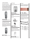
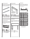
NOTE: DIAGRAMS & ILLUSTRATIONS ARE NOT TO SCALE.
8
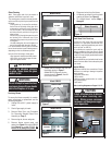
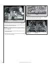
If the burner fl ame appearance differs greatly
from what is shown in Figure 13 (see Burner
Flame Appearance), some adjustment from
the factory setting for the air shutter gap may
be necessary (to compensate for variables
in the installation and fuel such as, BTU
value/composition, gas pressure, specifi c
gravity of gas, altitude, etc.).
See Table 5 on Page 8 for Burner Air Shutter
Adjustment Guidelines.
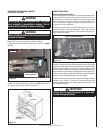
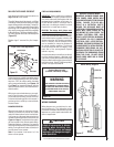
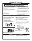
Initially, always position the air shutter to the
factory setting as shown in Figure 14 (adjust-
ment rod is located in the lower control area).
This can be done by moving the adjustment
rod up or down accordingly. Allow the burner
to operate for at least 15 minutes. Observe
the fl ame continuously. If it appears weak
or sooty as previously described, adjust the
air shutter to a more open position until the
proper fl ame appearance is achieved.
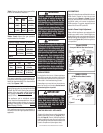
Burner Adjustment Procedure
Burner Air Shutter Adjustment
Adjustment Rod Up
(1/8" Open Position)
Air Shutter
Burner Tube
Adjusting Set Screw
Adjustment Rod Down
(full open position)
Figure 14
MAIN BURNER FACTORY AIR
SHUTTER OPENING SETTING
Model Gas Type Air Shutter Gap
EBVI30 Natural Gas 5/16" (7.94mm)
Propane 1/2" (12.7mm)
EBVI25 Natural Gas 1/16" (1.59mm)
Propane 1/2" (12.7mm)
WARNING
Air shutter adjustment should
only be performed by a qualifi ed
professional service technician.
CAUTION
The adjustment rod and nearby
appliance surfaces are hot. Exer-
cise caution to avoid injury while
adjusting fl ame appearance.
CAUTION
Carbon will be produced if the air shutter is closed too much. Any
damage due to carboning resulting from improperly setting the air
shutter is not covered under the warranty.
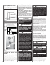
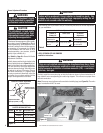
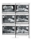
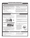
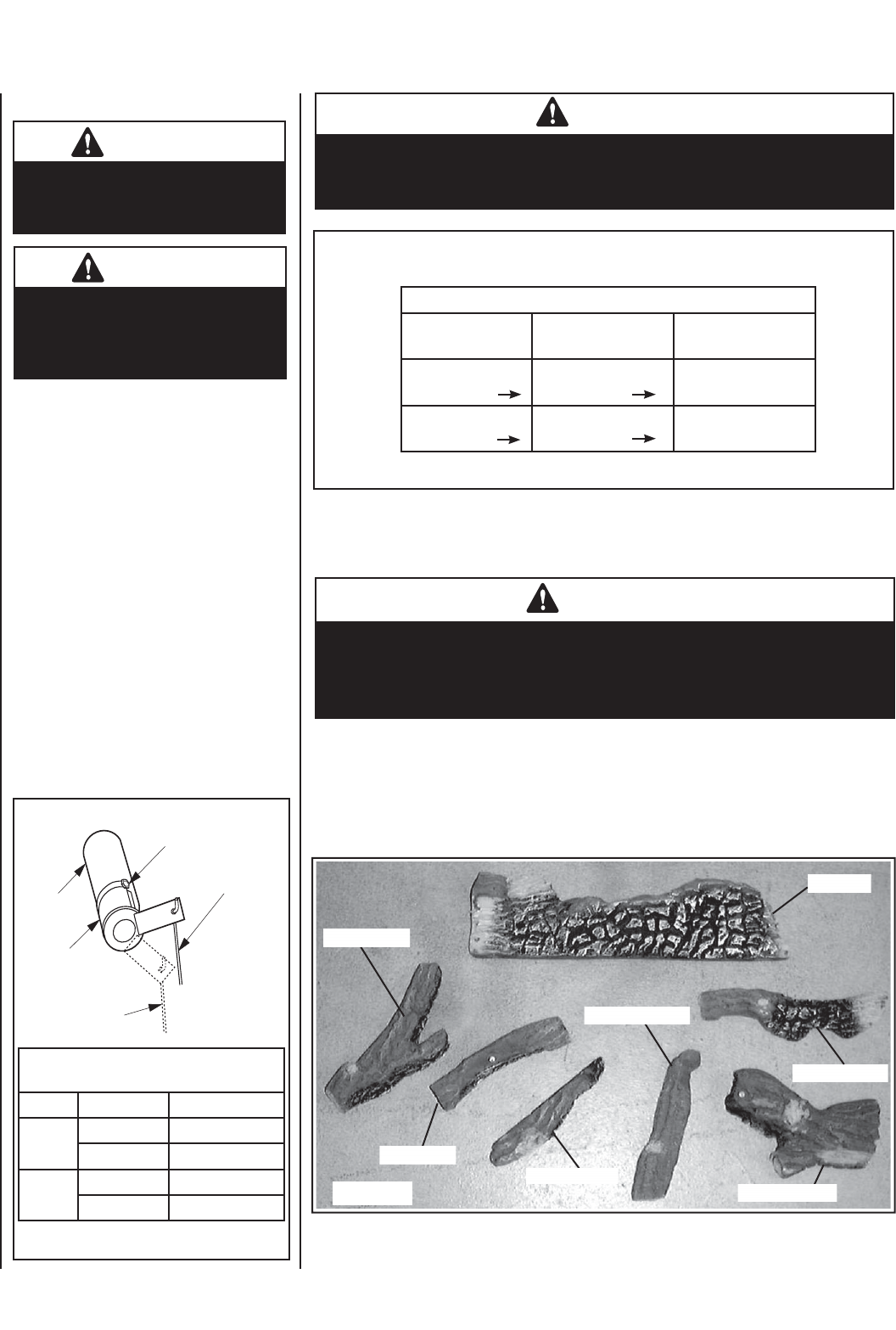
LOGS, VERMICULITE AND EMBERS
Carefully install the seven-piece log set into the fi rebox as shown in these instructions. All
logs should fi t onto corresponding pins and/or log stoppers. This will ensure a proper fl ame
and safe combustion.
Note: Place some vermiculite around burner before installing logs (see Figure 24). The entire
bag of vermiculite will NOT be used.
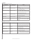
The following chart is provided to aid you in achieving the correct air shutter adjustment
for your installation.
Table 5
Air Shutter Adjustment Guidelines
Amount of
Primary Air
Flame Color Air Shutter
Adjustment
If air shutter is
closed too far
Flame will be orange Air shutter gap should
be increased
If air shutter is open
too far
Flame will be blue Air shutter gap should
be decreased
WARNING
If logs are not installed according to the directions shown here, fl ame
impingement and improper combustion could occur and result in soot
and/or excessive production of carbon monoxide (CO) - a colorless,
odorless, toxic gas.
Top Left Log
Front Center Log
Top Right Log
Rear Log
Front Right Log
Front Left Log
Center Log
Figure 15
Installation Instructions