


NOTE: DIAGRAMS & ILLUSTRATIONS ARE NOT TO SCALE.
3
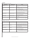
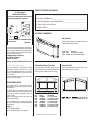
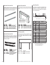
Table 2 shows the main burner gas orifi ce
size for the elevations indicated.
Model
No.
Orifi ce Size Elevation
Feet
(meters)
Nat.
Gas
Prop.
Gas
EBVI25 #41
(.096")
#53
(.0595")
0-4500
(0-1372)
EBVI30 #37
(.104")
1/16"
(.0625")
0-4500
(0-1372)
Table 2
Tables 3 and 4 show the gas pressure
requirements for all models:
Inlet Gas Supply Pressure (all models)
Fuel # Minimum Maximum
Natural Gas 4.5" WC
(1.12 kPa)
10.5" WC
(2.61 kPa)
Propane 11.0" WC
(2.73 kPa)
13.0" WC
(3.23 kPa)
Table 3
Manifold Gas Supply Pressure (all models)
Fuel # Low High
Natural
Gas
(Lo) 1.6" WC
(.40 kPa)
(Hi) 3.5" WC
(.87 kPa)
Propane (Lo) 6.3" WC
(1.57 kPa)
(Hi) 10.0" WC
(2.49 kPa)
Table 4
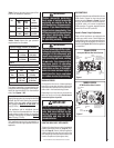
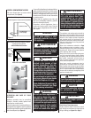
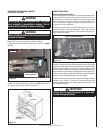
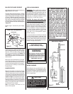
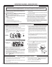
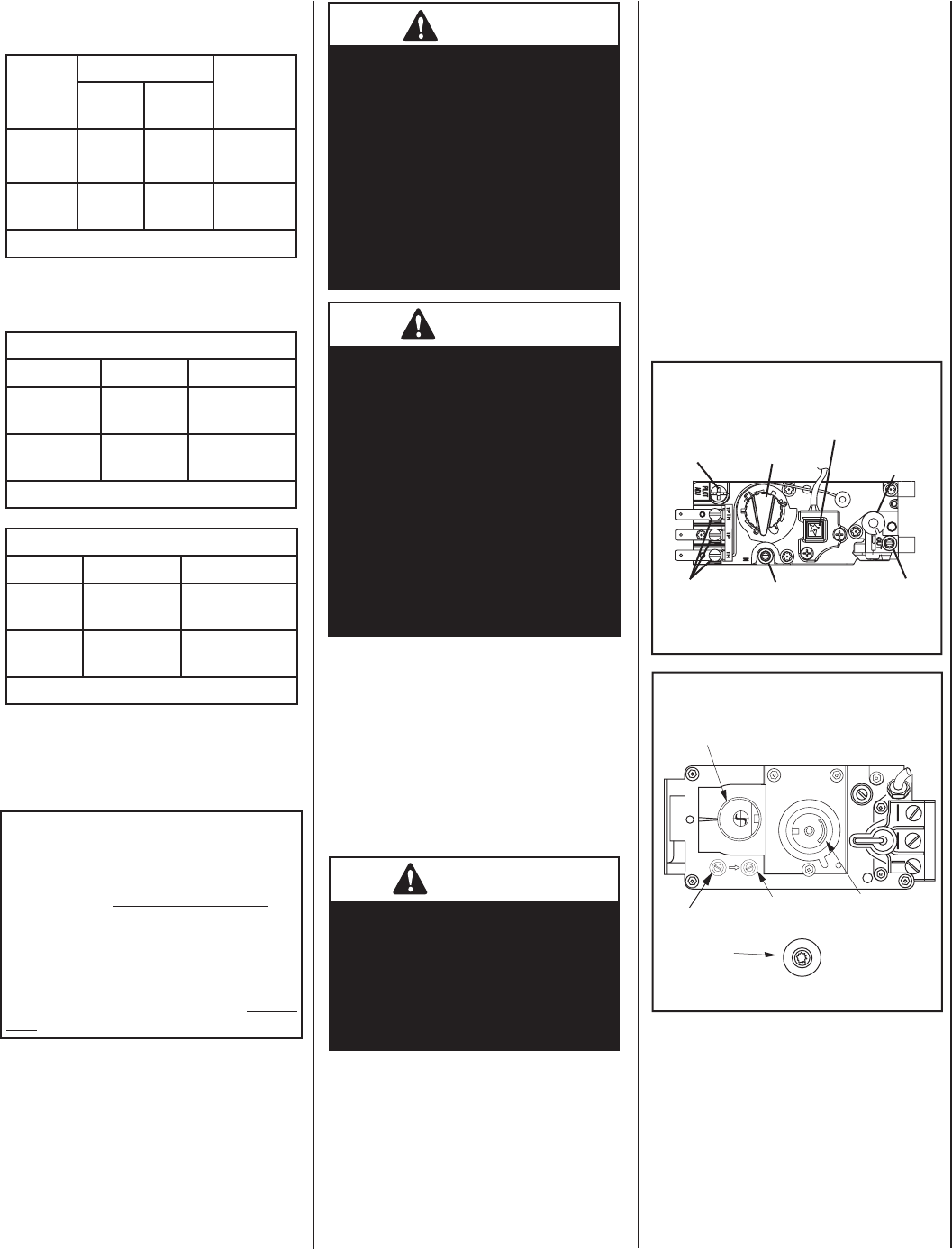
Test gauge connections are provided on the
front of the millivolt gas control valve (identi-
fi ed IN for the inlet and OUT for the manifold
side). See Figures 1 & 2.
This appliance must not be connected to a
chimney or fl ue serving a separate solid-fuel
appliance.
This appliance must be isolated from the gas
supply piping system (by closing its individual
manual shut-off valve) during any pressure
testing of the gas supply piping system at
test pressures equal to or less than 1/2
psig (3.5 kPa).
This appliance and its individual shut-off
valve must be disconnected from the gas
supply piping system during any pressure
testing of that system at pressures greater
than 1/2 psig (3.5 kPa).
WARNING
Carbon monoxide poisoning:
Early signs of carbon monoxide
poisoning are similar to the fl u
with headaches, dizziness and/or
nausea. If you have these signs,
obtain fresh air immediately. Turn
off the gas supply to the appliance
and have it serviced by a quali-
fi ed professional, as it may not
be operating correctly.
WARNING
Failure to comply with the instal-
lation and operating instructions
provided in this document will
result in an improperly installed
and operating appliance, voiding
its warranty. Any change to this
appliance and/or its operating
controls is dangerous. Improper
installation or use of this appli-
ance can cause serious injury or
death from fi re, burns, explosion
or carbon monoxide poisoning.
BURN-IN PERIOD
During the fi rst few burns of these appliances
there will be some odor due to the curing of the
high temperature paint and burning off of lubri-
cants used in the manufacturing process.
Depending on your use, the burn-in period may
take a few hours or a few days. Do not turn on
blower during Burn-In period.
IMPORTANT
Keep your house well ventilated
during the curing process. The
odor and haze emitted by the
curing process can be quite
noticeable and may set off a
smoke detector.
O
N
O
F
F
P
I
L
O
T
L
O
H
I
Figure 1
GAS CONTROL
KNOB
CONVERTIBLE
HI/LO REGULATOR
(adjusts fl ame height
and heat output)
INLET
PRESSURE
TAP
PILOT
ADJUSTMENT
SCREW
WIRING
TERM-
INALS
OUTLET
PRESSURE
TAP
Model EBVI30
Honeywell Millivolt Gas Valve Controls
TP/TH
PIEZO
IGNITER
TH
TP
H
I
L
O
W
TPTH TP TH
P
I
L
O
T
P
I
L
O
T
O
N
it
O
F
F
IN
OUT
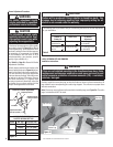
Figure 2
MODEL EBVI25
SIT Millivolt Gas Valve Controls
GAS CONTROL
KNOB
INLET
PRESSURE
TAP
OUTLET
PRESSURE
TAP
CONVERTIBLE
HI/LO REGULATOR
(adjusts fl ame height
and heat output)
PIEZO
IGNITER
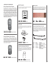
GAS CONTROLS
These millivolt appliances are fi tted with a burner
Off/On Switch, located on the side surround
panel as shown in Figure 4 on Page 4. Once the
pilot is lit, and valve knob is in the ON position,
the Off/On switch will control the appliance
Off/On operation. To operate, toggle the switch
between its ON and OFF positions.
Variable Flame Height Adjustment
These millivolt appliances are equipped with
variable gas control valves. Flame height may
be adjusted through a range between fi xed low
and high settings by rotating the HI/LO knob on
the valve (see Figures 1 & 2) while the appliance
is in operation.
LIGHTING MILLIVOLT APPLIANCES
To light millivolt appliances refer to the detailed
lighting instructions found on Page 15 (Eng-
lish) and Page 16 (French). Millivolt appliance
lighting instructions may also be found on the
pull-out lighting instruction labels located in the
control compartment (below glass door).