6
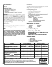
Pre-Installation
features
Installation Options
Manufactured (Mobile) Home
Natural Gas Or Propane (LP)
Bedrooms
Optional Wall-mounted Or Remote Thermostat
Electrical
The standard fan motor requires 120 Volts AC for operation.
The fireplace is not dependent on the fan or an outside elec
-
trical supply to operate.
WARNING - Electrical Grounding
Instructions - This appliance is equipped with a three-prong
(grounding) plug for your protection against shock hazard
and should be plugged directly into a properly grounded
three-prong receptacle. Do not cut or remove the ground-
ing prong from this plug.
Millivolt Valve
This insert is operated with a millivolt valve and therefore
burns even during a power outage.
Fuel
This insert comes from the factory equipped to burn natural
gas at a specified elevation. The insert can be converted
to burn LP (liquid propane) by installing a conversion kit.
Only Lennox Hearth Products conversion kits can be used
to convert from NG to LP or LP to NG. Contact your Lennox
Hearth Products dealer for details.
paCkaging list
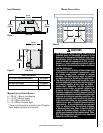
To install a Ravenna™ insert, an insert body, face, surround
(flange) kit, and brick panel are required.
Insert Body Packaging List
1 Insert Body with Burner Cassette
1 Set of Refractory Brick Panels
1 Log Set
1 Ravenna 40 orifice (additional clearance necessary!!!
- see clearances for Ravenna 40)
1 Bag of Embers
1 Fasteners: 6 slotted 1/4" truss screws
6 speed nuts
9 spring clips
3 plastic adhesive wire restraints
1 Installation and Operation Manual
Decorative Faces - One Required
Traditional Arch inset
Foundry Screen
Cast pillar
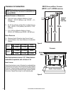
Surround Kits - One Required
Traditional 1-pc. (41"W x 29"H)
Traditional 3-pc.(41"W x 29"H, 48"W x 29"H, 41"W x
33"H or 48"W x 33"H)
Cast Iron (45-1/2"W x 30"H-Cast Pillar face only)
Surround Kit Contents
1 Top Surround
2 Side Surrounds
3 Gold or Nickel Plated Trim Pieces
2 Elbowed Trim Fasteners
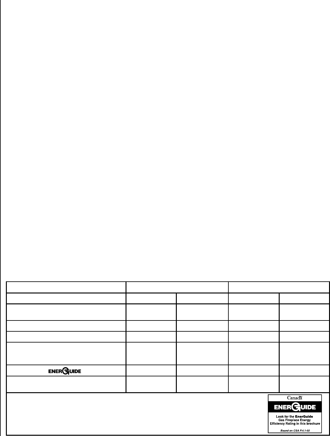
RATINGS Ravenna 40 (RDV40) Ravenna 33 (RDV33)
NATURAL GAS LP GAS NATURAL GAS LP GAS
Max/Min Input BTUh 0-2,000 Feet
(0-610 M)
u
40,000/28,000 37,500/26,000 33,000/24,000 33,000/24,000
Manifold Pressure (IN. WC) 3.5 10.0 3.5 10.0
Min. Inlet Pressure (IN. WC) 5.0 10.5 5.0 10.5
Maximum heat output BTUs/hour-
steady state (depending on vent
configuration)v
83% 83% 83% 83%
P4 Efficiency
w
67.17% 69.07% 65.55% 67.80%
Orifice (DMS) 0-2,000 Feet (0-610
M)u
1/8” #49 #36 #51
uUnit factory equipped for 0-2000 FT/0-610 M, In Canada 0-4500 FT/0-1370 M
vThe Steady State Efficiency numbers based on maximum vent configuration.
wTested to CSA P.4.1-02 “Testing Method for Measuring Annual Fireplace Efficiency.
Electrical Rating: 120 VAC, 60 HZ, Less Than 2 Amps


