


NOTE: DIAGRAMS AND ILLUSTRATIONS ARE NOT TO SCALE.
9
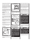
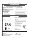
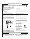
WIRING DIAGRAMS
Wiring diagrams are provided here for reference purposes only. This information is also provided on schematics attached directly to the appliance
on a pullout panel located within the control compartment.
CAUTION: LABEL ALL WIRES PRIOR TO DISCONNECTION WHEN SERVICING CONTROLS. WIRING ERRORS CAN CAUSE IMPROPER AND DAN-
GEROUS APPLIANCE OPERATION.
WARRANTY INFORMATION
Your gas appliance is covered by a limited twenty
year warranty. You will fi nd a copy of the war-
ranty accompanying this manual. Please read
the warranty to be familiar with its coverage.
Retain this manual. File it with your other docu-
ments for future reference.
REPLACEMENT PARTS
A complete parts list is found at the end of
this manual. Use only parts supplied from the
manufacturer.
Normally, all parts should be ordered through
your Lennox Hearth Products Distributor or
Dealer. Parts will be shipped at prevailing prices
at time of order.
Product Reference Information
We recommend that you record the following important information about your stove. Please
contact your Lennox Hearth Products Dealer for any questions or concerns. For the number of
your nearest Lennox Hearth Products Dealer, please call 1-800-9-Lennox
Your Stove's Model Number __________________________________________
Your Stove's Serial Number ___________________________________________
The Date On Which Your Stove Was Installed _____________________________
The Type of Gas Your Stove Uses ______________________________________
Your Dealer's Name ________________________________________________
If you encounter any problems or have any ques-
tions concerning the installation or application
of this system, please contact your distributor,
or Lennox directly:
Lennox Hearth Products
1110 West Taft Avenue
Orange, CA 92865
Visit us at www.LennoxHearthProducts.com
When ordering repair parts, always give the
following information:
1. The model number of the appliance.
2. The serial number of the appliance.
3. The part number.
4. The description of the part.
5. The quantity required.
6. The installation date of the appliance.
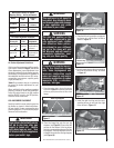
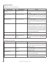
If any of the original wire as supplied must be replaced,
it must be replaced with Type AWM105°C – 18 GA. wire.
Thermopile
TH
TP
TH
TP
* ON/OFF Switch, Optional
Thermostat Remote
Control Receiver
* SWITCH
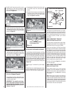
Figure 20
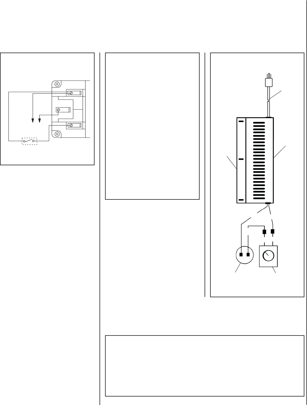
Blower
Mounting
Bracket
Black
Black
White
White
Fan Disc
Rheostat
Blower
Assembly
(Shown
Rotated 90
Degrees CCW)
Black
Power Cord
Blower Wiring Diagram
Optional Room Air Blower
SIT Millivolt Wiring Diagram
Figure 22
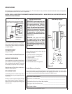
IMPORTANT:
Ground supply wire must
be connected to the green wire attached
to the green ground screw. Failure to
do so will result in a potential safety
hazard. The appliance must be electri-
cally grounded in accordance with local
codes or, in the absence of local codes,
the National Electrical Code, ANSI/NFPA
70 - latest edition. (In Canada, the cur-
rent CSA C22-1 Canadian Electrical Code
- latest edition.
WARNING: The power cord must
be plugged directly into a properly
grounded three-prong 120 Volt, 60 Hz
wall receptacle. Do not cut or remove
the grounding prong from this plug. Do
not route power cord under or in front
of appliance.