


NOTE: DIAGRAMS AND ILLUSTRATIONS ARE NOT TO SCALE.
5
H
I
L
O
W
TPTH TP TH
P
I
L
O
T
P
I
L
O
T
O
N
it
O
F
F
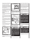
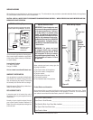
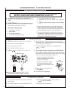
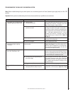
HI / LO Knob
Variable Flame Height Adjustment
Manifold Pressure Port
Inlet
Pressure
Port
Main Gas
Control Knob
Piezo Igniter
IN
OUT
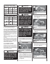
Test gage connections are provided on the front
of the millivolt gas control valve (identifi ed IN for
the inlet and OUT for the manifold side).
These appliances must be isolated from the
gas supply piping system (by closing their
individual manual shut-off valve) during any
pressure testing of the gas supply piping
system at test pressures equal to or less
than 1/2 psig (3.5 kPa).
These appliances and their individual shut-off
valves must be disconnected from the gas
supply piping system during any pressure
testing of that system at pressures in excess
of 1/2 psig (3.5 kPa).
OPERATION AND CARE OF YOUR
APPLIANCE
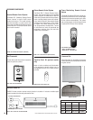
Appliance operation may be controlled through
a remotely located optional wall thermostat or
remote control.
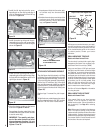
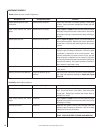
In lieu of remote or remote wall thermostat
operation, the appliance must be operated
directly through the on/off rocker switch located
on the upper right side of the rear shield. See
Figure 1.
If your millivolt appliance is equipped with an
optional wall thermostat kit or remote control
kit and the pilot is lit, the appliance main burner
may be turned on and off with the wall thermostat
or remote control.
Always keep the appliance area clear and free
from combustible materials, gasoline and other
fl ammable liquids.
Remember, Millivolt appliances have a continu-
ous burning pilot fl ame. Exercise caution when
using products with combustible vapors.
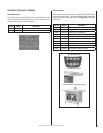
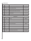
Control Compartment Access
The gas controls can be found behind the lower
access door. To access, pull the door open
(see Figure 2).
Millivolt appliances will be fi tted with the gas
control valve shown in Figure 3. Familiarize
yourself with the gas control valve that your
appliance uses.
Figure 3
SIT Millivolt Gas Valve Controls
Burner
On /Off
Switch
Top View
Front
Figure 1
Burner On/Off Switch
GAS CONTROLS
Lower Access Door
Pull open lower door to access Valve Contols
Lower Access
Door
Figure 2
FRONT GLASS ENCLOSURE PANEL,
REMOVAL AND INSTALLATION.
These are direct-vent appliances. They are
designed to operate only with the front glass
enclosure panel properly installed. Generally, the
glass enclosure panel should not be removed
except to gain access to the components within
the fi rebox, and the appliance may only be oper-
ated without the front glass enclosure panel in
place for very brief periods of time during initial
appliance checkout and adjustment.
During this appliance checkout and adjust-
ment period, a potential safety hazard exists
- EXERCISE EXTREME CAUTION to prevent
the occurrence of any burn injuries from the
exposed fl ames or hot surfaces. Also note,
that while the front glass enclosure panel is
removed, the fl ame will appear to be smaller
than normal.
WARNING
Never operate the appliance
without the glass enclosure
panel in place and secure. Do
not operate appliance with the
FRONT glass panel cracked,
broken or missing. Replacement
panels are available through
your local Lennox Hearth Prod-
ucts dealer and must be installed
by a licensed or qualifi ed service
technician.
1. Remove the trivet, then the cast iron stove
top by carefully lifting them up and off
and setting them aside (READ CAUTION
BELOW).
CAUTION
The cast iron stove top is very
heavy and may require a mini-
mum of two people to lift; one
person on each side (the CI1500
series cast top weighs ~20
pounds and the CI2500 series
cast top weighs ~40 pounds).
WARNING
Do not attempt to substitute the
materials used on this door, or
replace cracked or broken glass
with any materials other than
those provided by the appliance
manufacturer. The glass door
of this appliance must only be
replaced as a complete unit as
provided by the manufacturer.
Do not attempt to replace broken,
cracked or chipped glass sepa-
rately.
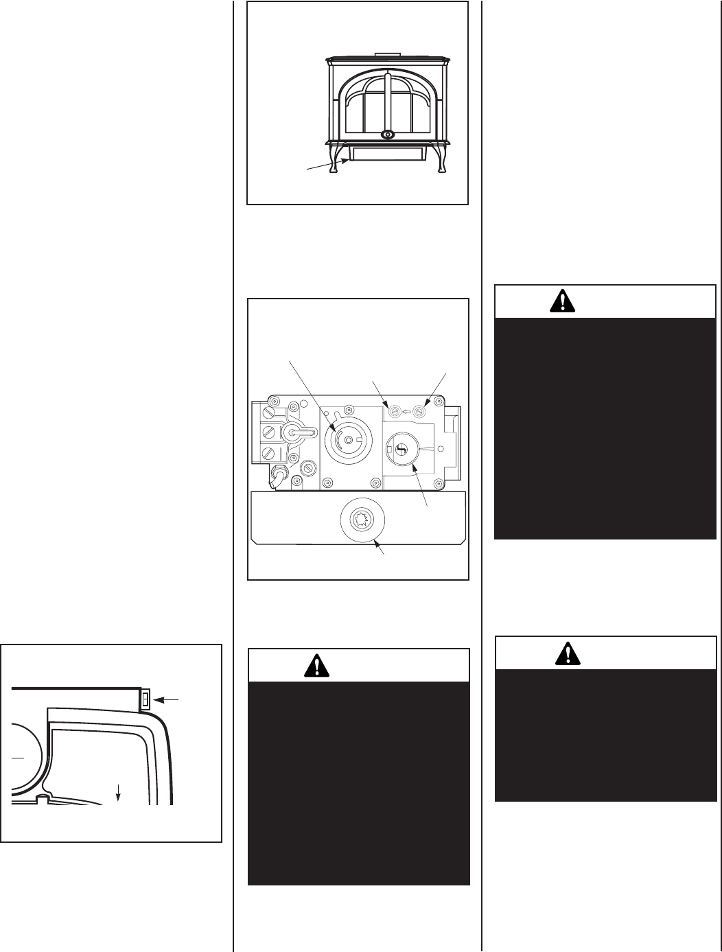
2. Locate and open the 2 latches as shown in
Figure 4 (locate below the stove body).