


NOTE: DIAGRAMS AND ILLUSTRATIONS ARE NOT TO SCALE.
7
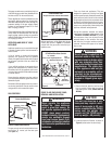
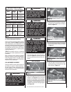
Air Shutter Adjustment Guidelines:
If the burner fl ame appearance differs greatly
from what is shown on Page 6 (see Burner
Flame Appearance), some adjustment from
the factory setting for the air shutter gap may
be necessary (to compensate for variables in
the installation and fuel such as, BTU value /
composition, gas pressure, specifi c gravity
of gas, altitude, etc.).
Table 6 is provided to aid you in achieving
the correct air shutter adjustment for your
installation.
When satisfi ed that the appliance operates
properly, proceed to fi nish the installation.
Leave the control knob in the ON position
and the ON/OFF switch in the OFF position.
Close the lower access door.
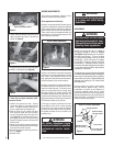
LOG AND EMBER PLACEMENT
Carefully install this seven-piece log set into
the fi rebox as shown in these instructions.
All logs should fi t onto corresponding pins
and/or log stoppers. This will ensure a proper
fl ame and safe combustion.
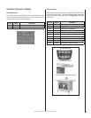
Main Burner Factory Air Shutter
Opening Setting - Inches (millimeter)
Model Natural
Gas
Propane
Gas
CI1500DVF
5/16"
(7.93 mm)
5/8"
(15.9 mm)
CI2500DVF
1/2"
(12.7 mm)
5/8"
(15.9 mm)
Table 5
Air Shutter Adjustment Guidelines:
Amount of
Primary Air
Flame
Color
Air Shutter
Adjustment
If air shutter is
closed too far
Flame will
be yellow
Air shutter
gap should be
increased
If air shutter is
open too far
Flame will
be blue
Air shutter
gap should be
decreased
Table 6
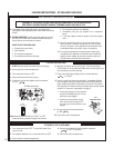
Refer to Figure 8
Figure 9
Ember
Strip
Rear Log Stoppers
1. Place the ember strip in front of the burner
as shown in Figure 9. It should be positioned
all the way back (toward the sub-fl oor front
fl ange).
WARNING
Logs get very hot and will remain
hot up to one hour after gas
supply is turned off. Handle
only when logs are cool. Turn
off all electricity to the appliance
before you install logs.
WARNING
This appliance is not meant to
burn wood. Any attempt to do so
could cause irreparable damage
to your appliance and prove
hazardous to your safety.
WARNING
The size and position on the
log set was engineered to give
your appliance a safe, reliable
and attractive fl ame pattern.
Any attempt to use a different
log set in the stove will void
the Warranty and will result in
incomplete combustion, soot-
ing, and poor fl ame quality.
WARNING
If logs are not installed accord-
ing to the directions shown
here, fl ame impingement and
improper combustion could
occur and result in soot and/or
excessive production of carbon
monoxide (CO), a colorless,
odorless, toxic gas.
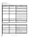
Rear
Log
Figure 10
2. Place the largest log onto the rear log
stoppers (see Figure 9). Ensure that the
grooves on the bottom of the log aligns
onto the corresponding places on the rear
log stoppers. Push the log back so that it
is against the back of the rear log stoppers
(see Figure 10).
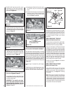
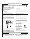
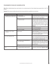
Left Front Log
Figure 11
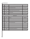
Center
Log
Piece
Figure 12
4. Place the center log over the corresponding
pins next to the front left log as shown
in Figure 12.
3. Place the left front log onto the correspond-
ing burner pin and sub-fl oor left tab as
shown in Figure 11.
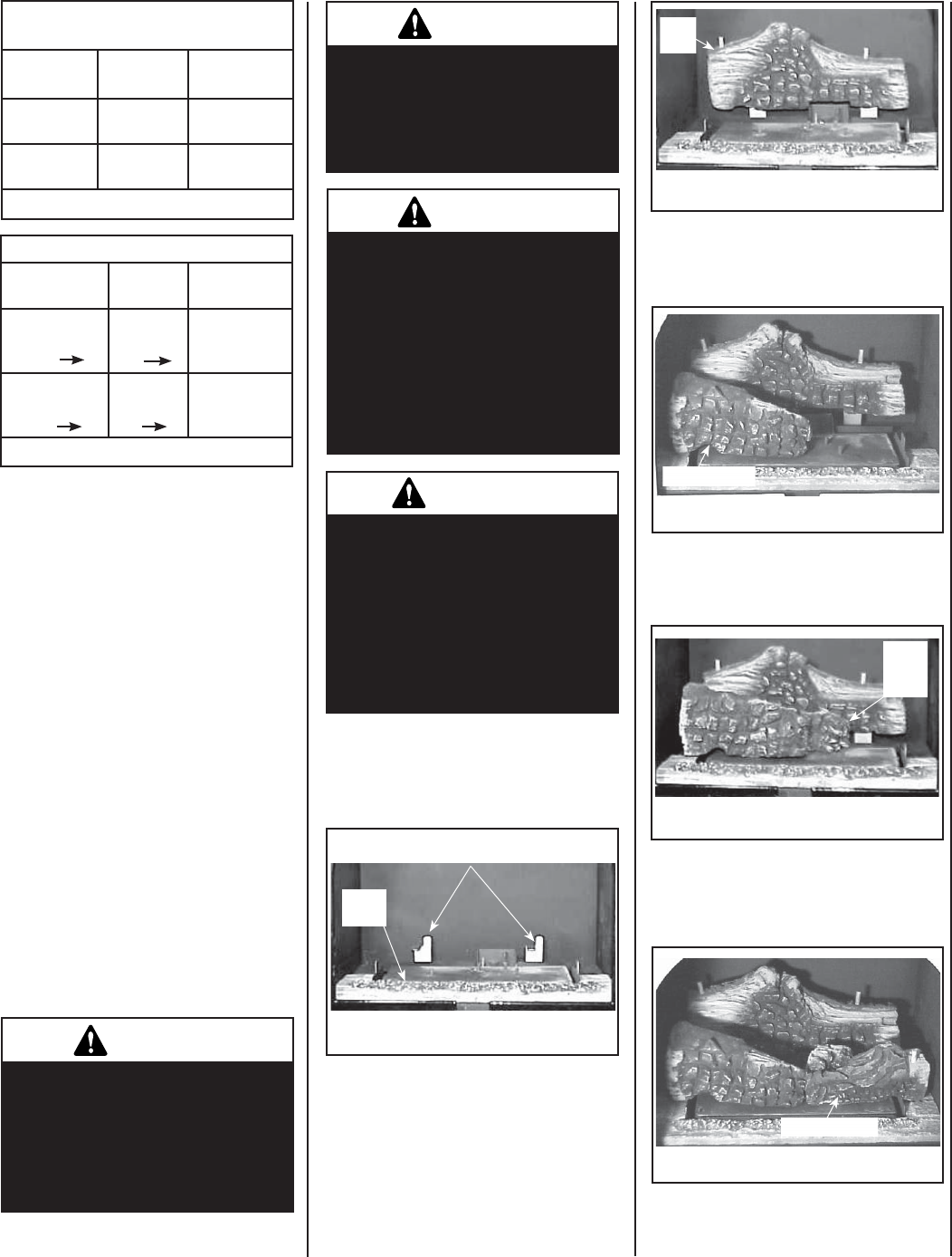
5. Install the right front log onto the corre-
sponding burner pin and sub-fl oor right
tab as shown in Figure 13.
Right Front Log
Figure 13