


28
NOTE: DIAGRAMS & ILLUSTRATIONS NOT TO SCALE.
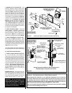
Step 1. Turn off the gas supply to the appliance.
Open the bottom drop-down door. Open it
(See
Figure 46 on page 23 )
by pushing in simulta-
neously the left and right top corners of the door.
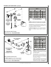
Burner Assembly
Gas Valve
Assembly
Orifice
noisrevnoCsaGenaporPoTlarutaN
tiK
.oNsledoMepyTtinU
golataC
.oN
0353VDEtlovillim26L58
5304VDEtlovillim36L58
0454VDEtlovillim46L58
0353VDEcinortcele67L58
5304VDEcinortcele77L58
0454VDEcinortcele87L58
Figure 55
In Canada:
THE CONVERSION SHALL BE CARRIED OUT
IN ACCORDANCE WITH THE REQUIREMENTS
OF THE PROVINCIAL AUTHORITIES HAVING
JURISDICTION AND IN ACCORDANCE WITH
THE REQUIREMENTS OF THE CAN1-B149.1
AND .2 INSTALLATION CODE.
LA CONVERSION DEVRA ÊTRE EFFECTUÉE
CONFORMÉMENT AUX RECOMMANDATIONS
DES AUTORITÉS PROVINCIALES AYANT
JURIDICTION ET CONFORMÉMENT AUX
EXIGENCES DU CODE D'INSTALLATION CAN1-
B149.1 ET.2.
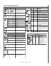
Gas conversion kits are available to adapt your
appliance from the use of one type of gas to the
use of another. These kits contain all the neces-
sary components needed to complete the task
including labeling that must be affixed to en-
sure safe operation.
Kit part numbers are listed here and the following
steps detail the conversion procedure.
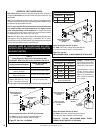
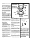
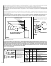
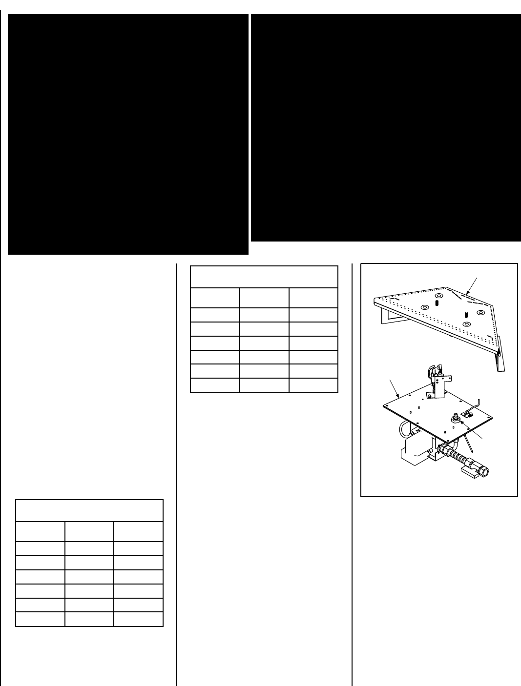
Step 3. Refer to
Figure 55
.
A. Above the burner, remove the two baffle
securing screws. Remove the baffle.
GAS CONVERSION KITS
noisrevnoCsaGlarutaNotenaporP
tiK
.oNledoMepyTtinU
golataC
.oN
0353VDEtlovillim96L58
5304VDEtlovillim07L58
0454VDEtlovillim17L58
0353VDEcinortcele38L58
5304VDEcinortcele48L58
0454VDEcinortcele58L58
WARNING: THIS CONVERSION KIT SHALL BE
INSTALLED BY A QUALIFIED SERVICE AGENCY IN
ACCORDANCE WITH THE MANUFACTURER'S IN-
STRUCTIONS AND ALL APPLICABLE CODES AND
REQUIREMENTS OF THE AUTHORIZED HAVING
JURISDICTION. IF THE INFORMATION IN THESE
INSTRUCTIONS IS NOT FOLLOWED EXACTLY, A
FIRE, EXPLOSION OR PRODUCTION OF CARBON
MONOXIDE MAY RESULT CAUSING PROPERTY
DAMAGE, PERSONAL INJURY OR LOSS OF LIFE.
THE INSTALLATION IS NOT PROPER AND COM-
PLETE UNTIL THE OPERATION OF THE CONVERTED
APPLIANCE IS CHECKED AS SPECIFIED IN THE
OWNER INSTRUCTIONS SUPPLIED WITH THE KIT.
THE QUALIFIED SERVICE AGENCY PERFORMING
THIS INSTALLATION ASSUMES RESPONSIBILITY
FOR THIS CONVERSION.
AVERTISSEMENT: CET ÉQUIPEMENT DE CONVERSION
SERA INSTALLÉ PAR UNE AGENCE QUALIFIÉE DE SERVICE
CONFORMÉMENT AUX INSTRUCTIONS DU FABRICANT ET
TOUTES EXIGENCES ET CODES APPLICABLES DE
L'AUTORISÉS AVOIR LA JURIDICTION. SI L'INFORMATION
DANS CETTE INSTRUCTION N'EST PAS SUIVIE
EXACTEMENT, UN FEU, EXPLOSION OU PRODUCTION DE
PROTOXYDE DE CARBONE PEUT RÉSULTER LE DOMMAGES
CAUSER DE PROPRIÉTÉ, PERTE OU BLESSURE
PERSONNELLE DE VIE. L'AGENCE QUALIFIÉE DE SERVICE
EST ESPONSABLE DE L'INSTALLATION PROPRE DE CET
ÉQUIPMENT. L'INSTALLATION N'EST PAS PROPRE ET
COMPLÉTE JUSQU'À L'OPÉRATION DE L'APPAREIL
CONVERTI EST CHÉQUE SUIVANT LES CRITÈRES ÉTABLIS
DANS LES INSTRUCTIONS DE PROPRIÉTAIRE
PROVISIONNÉES AVEC L'ÉQUIPEMENT.
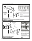
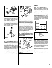
Millivolt Appliances
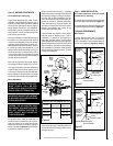
Step 4. SIT Systems - Refer to
Figure 56 on
page 29
and the instructions provided with the
kit. Using a Torx T20, remove and discard the
three pressure regulator mounting screws.
Remove the pressure regulator, spring, pop-
pet, diaphragm and bushing. Discard all re-
moved components. Ensure the rubber gasket
installed on the back of the replacement pres-
sure regulator is properly positioned and install
the new pressure regulator using the new screws
supplied with the kit. Tighten screws to 25 In.
lb. torque.
Open the bottom drop-down door. Open it
(See
Figure 46 on page 23 )
by pushing in simulta-
neously the left and right top corners of the
door. (The door is hinged at the bottom.) Re-
move the bottom compartment door by sliding
the hinge pin, located at the door’s left side, to
the right until it disengages from the left corner
post hole. Pull the door diagonally to the left,
away from the fireplace.
Remove the modesty panel.To remove the mod-
esty panel lift the modesty panel by the tab on
the panel’s right end, pull the right end of the
panel away from cabinet and then pull the panel
diagonally out of the corner post slots on the
left side of the unit. Remove the modesty panel
carefully, so that none of the wires become
loose or disconnected. Remove the front glass
door/frame from the appliance.
Step 2. Carefully remove the logs. Exercise
care so as not to break the logs.
B. Remove the two screws securing the trap-
ezoidal plate to the burner. Remove the plate.
C. Remove the burner assembly with attached
venturi tube.