


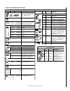


24
NOTE: DIAGRAMS & ILLUSTRATIONS NOT TO SCALE.
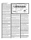
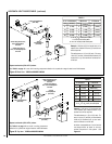
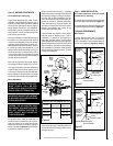
ELECTRONIC
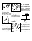
Proper Flame
Adjustment
Pilot
Nozzle
3/8 To 1/2 Inch
(9 mm to 13 mm)
Ground
Electrode
Flame Rod
Hot Surface
Igniter
Figure 47
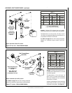
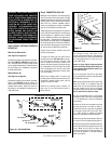
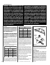
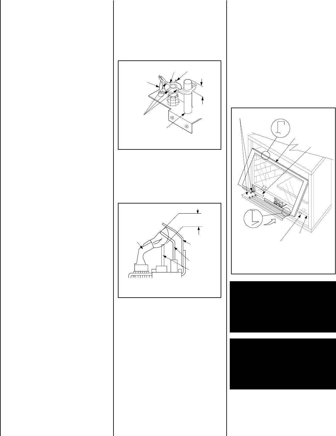
Glass Door Latch
Lower Compartment Door and Hinge
Glass Door
Firebox Floor
Bottom Vee-flange
Glass Door Frame
Top Flange
Glass Door Frame
Modesty
Panel
Figure 49
-
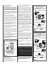
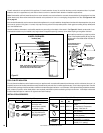
Figure 48
Millivolt Appliance Checkout
The pilot flame should be steady, not lifting or
floating. Flame should be blue in color with
traces of orange at the outer edge.
The top 3/8" (10 mm) at the pilot generator
(thermopile) and the top 1/8" min (tip) of the
quick drop out thermocouple should be en-
gulfed in the pilot flame.
INSTALLING THE GLASS DOOR
The flame should project 1" (25 mm) beyond
the hood at all three ports
(Figure 47).
Re-
place logs if removed for pilot inspection.
To light the burner; turn “ON” the remote wall
switch and rotate the gas valve control knob
counterclockwise to the “ON” position (“ON”
will be at the bottom side of the valve).
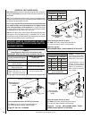
MILLIVOLT
Thermocouple
Hood
Ignitor Rod
³⁄₈" Min
(9 mm)
Thermopile
Pilot
Nozzels
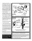
Step 7. INSTALLING CERAMIC EMBER
PANEL, LOGS AND GLOWING EMBERS
The logs are packaged in a carton located
within the firebox. One plastic bag of glow-
ing embers is located in the bottom com-
partment. Refer to the Log Set Placement
Supplement for detailed placement instruc-
tions for the ceramic ember panel, logs and
glowing embers.
Step 8. CHECKING APPLIANCE OPERATION
With gas line installed run initial system check-
out before closing up the front of the unit.
Follow the pilot lighting instructions provided
in the Homeowner's Care and Operation In-
structions. For piezo ignitor location see
Fig-
ure 46 on page 23
(millivolt appliances only).
Note: Lighting Instructions are also found on
the literature tag tied to the gas piping next to
the gas valve. To access the tag, open the
lower control compartment door (Figure 46 on
page 23 ) by pushing in simultaneously the left
and right top corners of the door. (The door is
hinged at the bottom.) Remove the bottom
compartment door by sliding the hinge pin,
located at the door’s left side, to the right until
it disengages from the left corner post hole.
Remove the modesty panel. To remove the
modesty panel, slide the panel forward until it
contacts the cabinet bottom panel, then lift
straight up and tilt forward. Remove the
modesty panel carefully, so that none of the
wires become loose or disconnected.
When first lighting the appliance, it will take
a few minutes for the line to purge itself of
air. Once purging is complete, the pilot and
burner will light and operate as indicated in
the instruction manual. Subsequent lighting
of the appliance will not require such purg-
ing. Inspect the pilot flame (remove logs, if
necessary, handling carefully).
WARNING: HANDLE THIS GLASS WITH
EXTREME CARE! THE GLASS PANEL IS
SUSCEPTIBLE TO DAMAGE — DO NOT
SCRATCH WHILE HANDLING OR WHILE
RE-INSTALLING THE GLASS DOOR
FRAME.
WARNING: DO NOT OPERATE APPLI-
ANCE WITH THE GLASS FRONT RE-
MOVED, CRACKED OR BROKEN. RE-
PLACEMENT OF THE GLASS SHOULD
BE DONE BY A LICENSED OR QUALIFIED
SERVICE TECHNICIAN.
Step 9. INSTALLING THE GLASS DOOR
To access the glass door securing latches,
first open the lower control compartment
door (
Figure 49
) by pushing in simultaneously
the left and right top corners of the door. (The
door is hinged at the bottom.) Remove the
bottom compartment door by sliding the hinge
pin, located at the door’s left side, to the right
until it disengages from the left corner post
hole. Pull the door diagonally to the left, away
from the fireplace.
Electronic Appliance Checkout
To light the burner, turn ‘ON’ the optional
remote wall switch and turn the gas control
switch to the “ON” position. Ensure the ignitor
lights the pilot. The pilot flame should engulf
the flame rod as shown in
Figure 48
.
Retrieve the glass door. Visually inspect the
gasket on the backside of the frame. Gasket
surface must be clean, free of irregularities and
seated firmly.
Position the door in front of the firebox opening
with the bottom of the door held away from the
fireplace
(Figure 49 )
. Hook the top flange of
the door frame over the top of the firebox frame.
Let the bottom of the door frame swing gently
in towards the fireplace ensuring that the gas-
ket seats evenly as the door frame draws shut.
Fasten the two latches located underneath the
firebox floor to the door's vee-flange. Close
both the latches securely.