


NOTE: DIAGRAMS & ILLUSTRATIONS NOT TO SCALE.
5
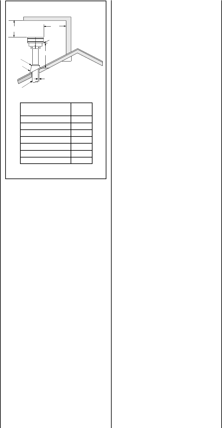
12
X
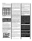
Roof Pitch is X/12
2 FT
MIN.
2 FT MIN.
Lowest
Discharge
Opening
H*
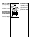
*H = MINIMUM HEIGHT FROM ROOF TO
LOWEST DISCHARGE OPENING OF VENT
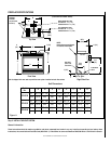
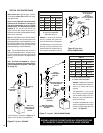
TERMINATION HEIGHTS FOR VENTS ABOVE
FLAT OR SLOPED ROOFS
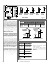
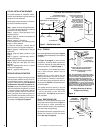
Horizontal Overhang
Vertical
Wall
Vent
Termination
Storm Collar
Concentric
Vent Pipe
Flashing
1 inch (25.4 mm) Minimum
Clearance to Combustibles
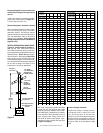
hctiPfooR
H
)teef(
21/6ottalF0.1
21/7ot21/6revO52.1
21/8ot21/7revO5.1
21/9ot21/8revO0.2
21/01ot21/9revO5.2
21/11ot21/01revO52.3
21/21ot21/11revO0.4
Figure 4
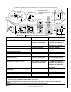
APPLIANCE AND VENT CLEARANCES
Vertical Vent Termination Clearances
VENT TERMINATION CLEARANCES
These instructions should be used as a guide-
line and do not supersede local codes in any
way. Install vent according to local codes,
these instructions, the current National Fuel
Gas Code (ANSI-Z223.1) in the USA or the
current standards of CAN/CGA-B149.1 and -
B149.2 in Canada.
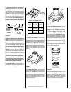
The appliance is approved with zero clearance
to combustible materials on all sides (as de-
tailed in
Table 2
), with the following excep-
tion: When the unit is installed with one side
flush with a wall, the wall on the other side of
the unit must not extend beyond the front edge
of the unit. In addition, when the unit is re-
cessed, the side walls surrounding the unit
must not extend beyond the front edge of the
unit. See
Figure 2
.
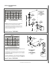
Terminate single vent caps relative to building
components according to
Figure 4
. Terminate
multiple vent terminations according to the
installation codes listed on this page.
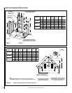
Horizontal Vent Termination Clearances
The horizontal vent termination must have a
minimum of 3" (76 mm) clearance to any
overhead combustible projection of 2-1/2" (64
mm) or less. See
Figure 5.
For projections
exceeding 2-1/2" (64 mm), see
Figure 5
. All
horizontal terminations may be located as
close as 6" (152mm) to any (non-combustible
and combustible) exterior sidewall. This dis-
tance may be decreased to 2" (51mm) for non-
combustible exterior sidewalls only, if the
SV4.5HT-2 termination is used. For additional
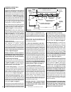
vent location restrictions refer to
Figure 8 on
page 7
.