


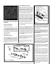


NOTE: DIAGRAMS & ILLUSTRATIONS NOT TO SCALE.
23
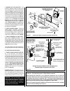
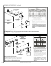
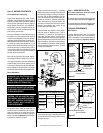
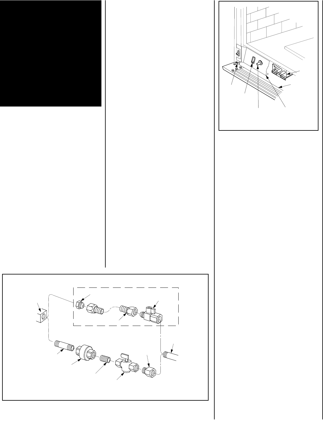
Figure 46
Piezo Ignitor
Gas
Valve
Modesty Panel
Control
Compartment
Access Panel
ON/OFF
Switch
Hinge Pin
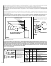
Gas
Stub
1/2" x 3/8" Flare
Shut-Off Valve
3/8" Flex Tubing
3/8" NPT x 3/8"
Flare Fitting
3/8" Nipple
3/8" Union
3/8" Close Nipple
3/8" Shut-Off Valve
1/2" x 3/8"
Reducer
Gas
Valve
Optional Gas Flex Line Connector
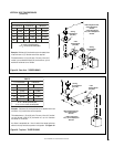
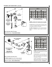
Figure 45 -
GAS CONNECTION
Step 6. CONNECTING GAS LINE
Make gas line connections. All codes require a
shut-off valve mounted in the supply line.
Fig-
ure 45
illustrates two methods for connecting
the gas supply. The flex-line method is accept-
able in the U.S., however, Canadian require-
ments vary depending on locality. Installation
must be in compliance with local codes.
These appliances are equipped with a gas flex
line for use (where permitted) in connecting the
unit to the gas line. A gas flex line is provided
to aid in attaching the direct vent appliance to
the gas supply. The gas flex line can only be
used where local codes permit. See
Figure 45
for flex line description. The flex line is rated for
both natural and propane gas. A manual shut
off valve is also provided with the flex line.
The gas control valve is located in the lower
control compartment.
To access the valve open the lower control
compartment door (
see Figure 46
) by push-
ing in the right top corner of the door. (The
door is hinged at the bottom.) Remove the
bottom compartment door by sliding the hinge
pin, located at the door’s left side, to the right
until it disengages from the left corner post
hole. Pull the door diagonally to the left, away
from the fireplace.
Remove the modesty panel. To remove the
modesty panel, slide the panel forward until it
contacts the cabinet bottom panel, then lift
straight up and tilt forward.
Remove the modesty panel carefully, so
that none of the wires become loose or
disconnected.
Secure all joints tightly using appropriate
tools and sealing compounds (ensure pro-
pane resistant compounds are used in pro-
pane applications).
Turn on gas supply and test for gas leaks,
using a gas leak test solution (also referred to
as bubble leak solution).
Note: Using a soapy water solution (50% dish
soap, 50% water) is an effective leak test
solution but it is not recommended, because
the soap residue that is left on the pipes/
fittings can result in corrosion over time. Never
use an open flame to check for leaks.
A. Light the appliance (refer to the lighting
instructions label in the control compartment
or in the Homeowner's Care and Operation
Instructions).
B. Brush all joints and connections with the
gas leak test solution to check for leaks. If
bubbles are formed, or gas odor is detected,
turn the gas control knob to the “OFF” posi-
tion. Either tighten or refasten the leaking
connection and retest as described above.
C. When the gas lines are tested and leak free,
be sure to rinse off the leak testing solution.
D. When the gas lines are tested and leak free,
observe the individual tongues of flame on the
burner. Make sure all ports are open and
producing flame evenly across the burner. If
any ports are blocked, or partially blocked,
clean out the ports.
The millivolt control valve has a 3/8"
(10 mm) NPT thread inlet port. The electronic
control valve has a 1/2" (13 mm) NPT thread inlet
port and is fitted with a 1/2" x 3/8" (13 mm x
10 mm) NPT fitting.
Step 5. WIRING - OPTIONAL FORCED AIR
BLOWER KIT
FBK-100 and FBK-200 Kits
(See Figure 43 on page 22)
-
An electrical outlet box is provided for the instal-
lation of the FBK-100, FBK-200 forced air blower
kits. Electrical power must be provided to this
box to operate these blowers. Install the blower
kits according to the installation instructions
provided with the kits.
FBK-250 Blower Kit
(See Figure 44 on page 22)-
An electrical outlet box is provided for the instal-
lation of the FBK-250 forced air blower kit.
Electrical power must be provided to this box to
operate these blowers. Install the blower kit
according to the installation instructions pro-
vided with the kit.
WARNING: ELECTRONIC MODELS OF
THESE APPLIANCES ARE EQUIPPED
WITH A THREE-PRONG (GROUNDING)
PLUG UTILIZED IN CONNECTING THE
ELECTRONIC COMPONENTS TO THE
JUNCTION BOX IN THE LOWER COM-
PARTMENT. THIS GROUNDING PLUG
PROVIDES PROTECTION AGAINST
SHOCK HAZARD AND SHOULD BE
PLUGGED DIRECTLY INTO THE PROP-
ERLY GROUNDED THREE-PRONG RE-
CEPTACLE. DO NOT CUT OR REMOVE
THE GROUNDING PRONG FROM THE
PLUG.