


NOTE: DIAGRAMS & ILLUSTRATIONS NOT TO SCALE.
29
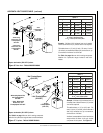
Pressure
Regulator
Remove
These
Components
Pilot
Orifice
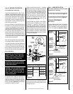
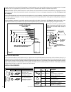
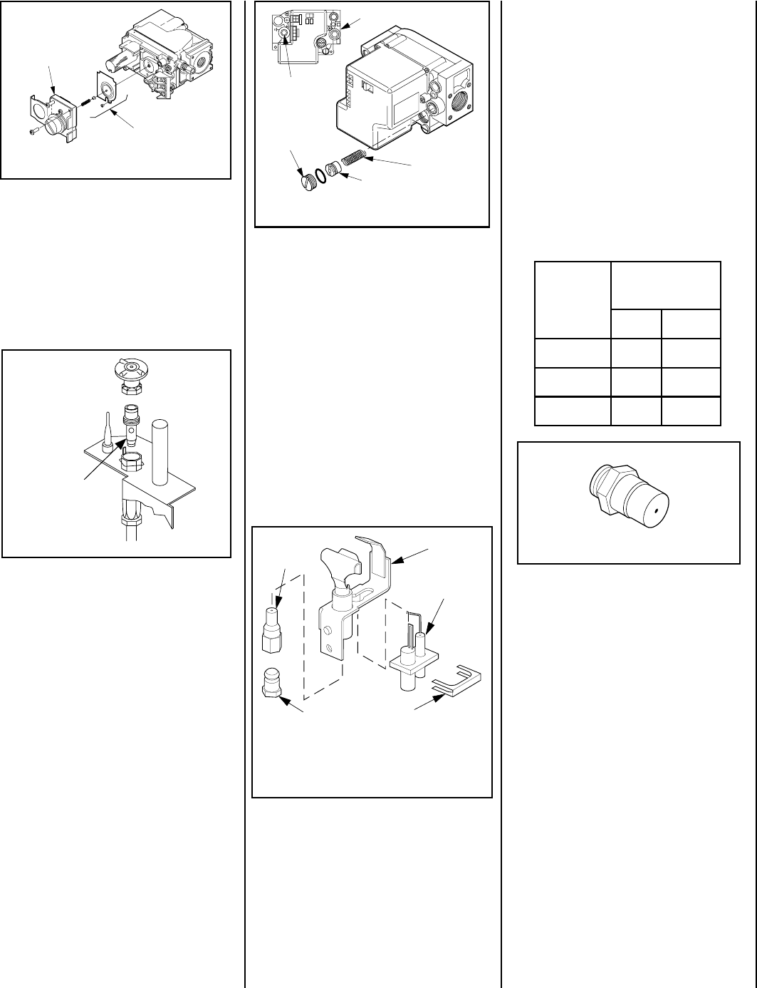
.oNledoM
ezisecifirO
larutaNenaporP
0353VDE04#35#
5304VDE63#25#
0454VDE33#15#
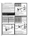
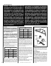
Figure 59
Figure 58
Figure 60
Figure 57
Figure 56
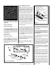
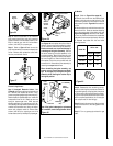
When reinstalling the ignitor assembly, use
extreme care to prevent damage and break-
age. Do not apply any leverage to the ignitor
assembly while restoring the retainer clip to
its original position.
Note: If the ignitor is damaged, a replacement
kit is available, order Catalog Number 87L54.
Retaining
Clip
Ignitor
Assembly
Pilot
Assembly
Pilot
Orifice
Flare Nut
Spring
Adjusting
Screw
Slotted
Cap
PSI
OFF
I
ON
CONTROL
IGNITE
Manifold
Pressure
Test Port
Inlet Pressure Test Port
Electronic Appliances
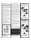
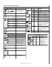
Step 7. Honeywell Electronic Valves - See
Figure 58
and the instructions provided with the
kit. Remove the slotted cap screw, o-ring,
pressure-regulating adjusting screw and spring.
Retain all parts for possible later use. Install new
components from the kit. Black cap and red
spring for propane gas units. Silver cap and
stainless steel spring for natural gas units. Be-
fore installing the cap, attach manometer to the
manifold side pressure test fitting and adjust
screw until pressure reads 3.5 inches water
column (0.87 kPa) for natural gas, and 10.0
inches water column (2.49 kPa) for propane gas.
Step 9. Reassemble the remaining compo-
nents by reversing the procedures outlined in
the preceding steps. Use pipe joint compound
or Teflon tape on all pipe fittings before install-
ing (ensure propane resistant compounds are
used in propane applications, do not use pipe
joint compounds on flare fittings).
Step 10. Attach the conversion label provided
in the conversion kit to the rating plate on the
appliance.
Step 11. Turn on gas supply and test for gas
leaks.
See
Figure 59
and replace the pilot orifice as
follows: Remove the ignitor assembly retainer
clip, and carefully remove the ignitor assembly.
Exercise extreme care to prevent damage to
or breakage of the ignitor assembly. Remove
the screw securing the pilot assembly to its
mounting bracket. Back off the flare nut at the
end of the pilot gas line to free the pilot assem-
bly from the gas line. Remove the pilot orifice
and replace it with the one provided with the
conversion kit. Reinstall the pilot assembly by
reversing the steps detailed here.
All Models
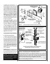
Step 8. (Refer to
Figure 55 on page 28
)
A. Remove the orifice from the manifold and
replace it with the one provided in the kit. See
the following table for orifice sizes for natural
and propane models
. Figure 60
illustrates the
orifice.
B. Retrieve the burner and hold the venturi tube
above the orifice . Place the shutter adjusting
rod in the propane slot of the shutter arm (see
Figure 50 on page 25)
. Set the burner assem-
bly into its position and secure the trapezoidal
plate with the two screws previously removed.
C. Reinstall the baffle with the two baffle
securing screws.
Step 5. Attach manometer to the manifold
side pressure test fitting and verify manifold
pressure reads 3.5 inches water column (0.87
kPa) for natural gas, and 10.0 inches water
column (2.49 kPa) for propane gas.
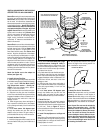
Step 6. Refer to
Figure 57
and remove the
pilot hood assembly to access the hexed pilot
orifice. Remove and replace the orifice with
the one provided with the kit.