


7
Installation should be done by a qualified service person.
Before connecting the appliance, turn off all gas appliances.
Close the main gas valve a
t the gas meter or LP tank. Make
certain there is good ventilation where the installation will be
made.
Installation should comply with all applicable building
codes and ANSI Z223.1, latest edition. Use PLP gas resistant
pipe compound to seal threaded joints.
An installer supplied,
design certified gas pressure
regulator must be installed to bring the gas supply pressure
down to 14" w.c. for LP gas or 11" for natural gas.
WARNING: Never connect an unregulated gas line to the
heater.
IMPORTANT: Check gas line pressure before connecting heater
to gas line. Gas line pressure must not be higher higher than
14" w.c. for LP gas or 11" for natural gas.
NOTE: The gas line connection can be made with 3/8”black or
steel pipe. Internally tinned copper tubing may be used in cer-
tain areas. Check your local codes. Use pipe of large enough
diameter to allow proper gas volume to heater. If pipe is too
small, undue pressure loss will occur.
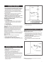
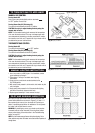
CAUTION: Use pipe joint sealant that is resistant to liquefied
petroleum gases. Install sediment trap in supply as shown in
Figure 6.
Locate sediment trap where it is within reach for cleaning.
Locate sediment trap where matter is not likely to freeze. A
sediment trap prevents moisture and contaminant's from going
into the heater controls. If the sediment trap is not installed or is
installed wrong, the heater may not operate properly.
Test for gas leaks with a mild soap and water solution. Apply
water/soap solution with brush only - do not over apply.
NEVER test with an open flame.
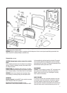
CONNECT TO GAS SUPPLY
Fig. 6 Gas line connection
PRESSURE TEST GAS SUPPLY
PIPING SYSTEM
The a
ppliance and its individual shut off (control) valve must
be disconnected from the gas supply piping system during any
pressure testing of the system at test pressure in excess of
1/2 psi (3.5 kPa).
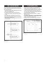
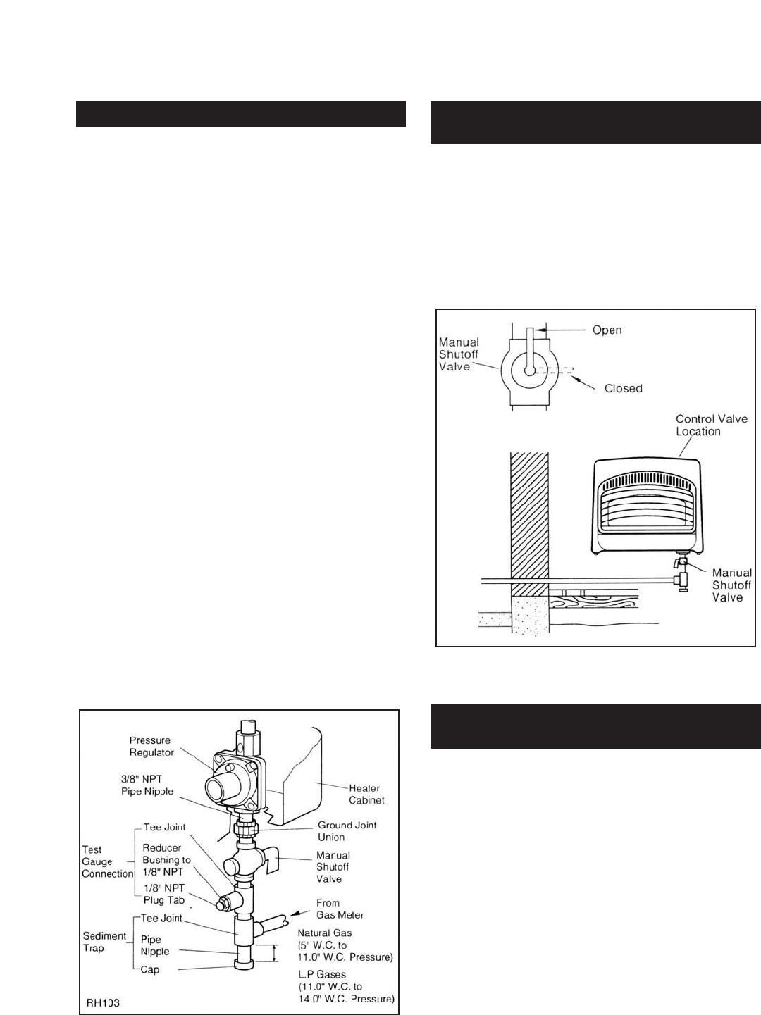
The appliance must be isolated from the gas supply piping
system by closing the individual manual shut-off valve (fig. 7)
during any pressure testing of the gas supply system at test
pressure equal to or less than 1/2 psi (3.5 kPa).
Fig. 7 Manual shut-off valve location.
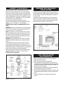
LEAK TESTING HEATER
GAS CONNECTION
1. Make sure control knob of heater is in the OFF position.
2. Open manual shut-off valve.
3. Open main gas valve located near gas meter.
4. check all joints from manual gas valve up to control valve
and including the manifold assembly. Apply the soap solution
around the connections, valve and tubing. Soap bubbles will
appear where a leak is present.
5. If a leak is present, immediately turn off gas supply, tighten
any leaky fittings, turn gas on and recheck.
6. To check burner and safety valve, the burner must be lit. (See
Operating Instructions) Check the rest of the connections for
leaks.
7. Turn off the heater prior to making any gas connection
repairs.