


4
KMACS 5 MANUAL
© 2003 KMDSI Document # 041112001
the electronic components. The KMACS 5 should
be treated as you would any expensive life support
equipment.
1.4.1 BREATHING AIR
SUBSYSTEM
The diver’s breathing air subsystem starts with the
supply tank yokes (K) and connects to the diver’s
supply manifold. The high pressure hoses with the
yokes are stored for transit by connecting them to
the posts on the panel inside the lid of the KMACS
5. The knurled knobs on the yokes should be tight-
ened until just snug. Excessive force should not be
applied.
1.4.2 PRINCIPLE
OPERATING FEATURES
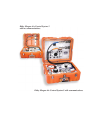
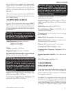
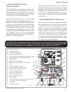
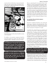
l. DIVE CONTROL PANEL (A)
The panel is the main frame to which the functional
components are mounted. In addition, the compo-
nent names and some instructions are on the panel.
The blue and orange lines (K, Q) on the panel
represent the flow paths of supply air from the two
high pressure hoses/yokes (S).
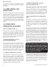
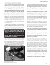
2. RED DIVER DEPTH GAUGE (C)
(PNEUMOFATHOMETER)
This gauge indicates the “red” diver depth. The red
diver pneumo valve knob (D), is turned to supply a
small volume of air to the small pneumo hose that
is part of the diver’s umbilical. The gauge reads
the pressure of the air in the pneumo hose. This
pressure, measured in feet (or meters) of sea water,
equals the water pressure at the diver’s depth.
3. UMBILICAL PRESSURE GAUGE (B)
This gauge (B) is connected to the low pressure air
supply system that supplies both umbilical fittings.
It indicates the breathing air pressure that is in both
the “red” and “white” diver umbilicals. When the air
supply is from high pressure tanks (such as scuba
tanks) the umbilical hose pressure can be varied by
turning the regulator adjustment knob (H)
4. WHITE DIVER DEPTH GAUGE (P)
(PNEUMOFATHOMETER)
This gauge indicates the “white” diver depth. The
white diver pneumo valve knob (O), is turned to
supply a small volume of air to the small pneumo-
hose that is part of the diver’s umbilical. The gauge
reads the pressure of the air in the pneumo-hose. This
pressure, measured in feet (or meters) of sea water,
equals the water pressure at the diver’s depth.
5. BLUE AIR SUPPLY FLOW INDICATOR
LINE
The “BLUE” air supply flow indicator line (Q) indi-
cates the flow path of breathing air from entry into
the KMACS 5 to exit to the diver’s umbilical(s) at
the fittings on the manifold (G). There are two high
pressure whips which are color coded BLUE and
ORANGE.
Starting from the high pressure air tank, the BLUE
air supply flows through the whip into the KMACS 5.
Following the BLUE flow indicator line (Q) it shows
the flow to the BLUE Breathing Air Supply Pressure
Gauge (M), then to the Breathing Air Supply Selec-
tor Valve which is controlled by the Breathing Air
Selector Valve Handle (I). The Selector Handle (I)
must be turned all the way “UP” until it stops for the
BLUE supply. This places the selector valve handle
in line with the flow path indicating the “BLUE” air
supply (Q). The ORANGE supply is off when the
Selector Handle is in the up position.
CAUTION: When using H.P. air, the selector
handle must be turned up until it stops for
BLUE supply or down until it stops for Orange
supply. Never allow the selector handle to
stay in the marked “H.P. OFF ZONE”. Both
high pressure air supplies are off in the
yellow striped H.P. OFF ZONE”.
After flowing through the Selector Valve the BLUE
air supply enters the Breathing Air Supply Regulator
(H) which reduces the high pressure breathing air
to an adjustable range between 115-225 pounds per
square inch (psi) (8-15.5 bars). The BLUE air sup-
ply then goes to both diver’s umbilicals through the
fittings on the manifold (G).