


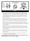

4. Using a pen or pencil, change the switches in each of the Kidde Wireless
devices to match the pattern you selected in step 3. Ensure that the
sequence is not reversed.
5. Power each unit after setting the ID by installing the batteries. The alarms
only read the ID that has been set when they are first supplied power. Any
changes to the switch after the unit is powered will not be recognized, and
will require the power to be removed for a minimum of 30 seconds before
powering again.
6. Push and hold the test button on each unit for at least 5 seconds, or until
all the devices produce an alarm. If all the units do not produce an alarm,
refer to the trouble-shooting section at the end of the user’s guide.
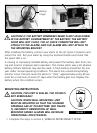
CAUTION: Due to the loudness of the alarm, always stand an arm’s
length away from the unit when testing.
7. Install the alarms in accordance with the user’s guide as described in section
1, and repeat step 6. Since wireless communication can be interrupted by
a number of factors, you must test your alarms weekly to ensure proper
communication between alarms.
8. Read the user’s guide and keep it in a safe place for future reference.
If your Wireless smoke alarms enter alarm mode, first check to see if
there is a fire. If a fire does not exist, and the test buttons have not
been activated on any of the units, it is likely that you are receiving
interference from a similar system nearby. In this case, repeat the above
steps and select a different dipswitch pattern, making sure to disconnect
power and remove the batteries before changing the switch positions.
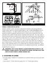
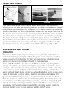
WIRING REQUIREMENTS
• This smoke alarm should be installed on a U.L. listed or recognized junction
box. All connections should be made by a qualified electrician and all wiring
used shall be in accordance with articles 210 and 300.3(B) of the U.S. National
Electrical Code ANSI/NFPA 70, NFPA 72 and/or any other codes having jurisdic-
tion in your area. The multiple station interconnect wiring to the alarms must
be run in the same raceway or cable as the AC power wiring. In addition, the
resistance of the interconnect wiring shall be a maximum of 10 ohms.
• The appropriate power source is 120 Volt AC Single Phase supplied from a
non-switchable circuit that is not protected by a ground fault interrupter.
WARNING: This alarm cannot be operated on power derived from a square
wave, modified square wave or modified sine wave inverter. These types of
inverters are sometimes used to supply power to the structure in off grid instal-