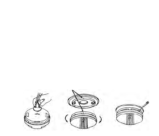
7.Install the alarm on the trim ring with the indicating marks aligned and rotate
the alarm in the direction of the “ON” arrow on the cover until the alarm
snaps in place (see figure 7).
8.Turn on the AC power. The green AC Power On Indicator should be lit when
the alarm is operating from AC power.
TAMPER RESIST LOCKING PIN: To make your heat alarm tamper resistant, a
locking pin has been provided with your alarm. Using this pin will help deter
children and others from removing the alarm from trim ring. To use the pin,
insert it into the hole in the side of the alarm after the alarm has been installed
on the trim ring (see figure 8).
NOTE: The tamper resist pin will have to be removed in order to change the bat-
teries. Use long nose pliers to pull the pin out of the hole. It is now possible to
remove the alarm from the trim ring.
After installation, TEST your alarm by pressing and holding the test button for
several seconds. You can also use a hand held hair dryer to test your heat alarm.
Complete details on this procedure are outlined in section 5.
CAUTION! Early warning fire detection is best achieved by the installation of
fire detection equipment in all rooms and areas of the household as follows: A
smoke alarm installed in each separate sleeping area (in the vicinity of - but out-
side of the bedroom) and heat or smoke alarms in the living rooms, dining
rooms, kitchens, hallways, attics, furnace rooms, closets, utility storage rooms,
basements, and attached garages.
To remove AC
connector,
squeeze
locking
arms and
pull.
Tamper resistant
locking pin
Alignment Marks
Remove
Install
FIGURE 6 FIGURE 7 FIGURE 8


