


10
Read Before Beginning Installation
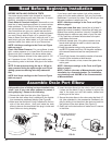
BEFORE INSTALLING CHECKS & TESTS
Your water supply needs to be checked for chemical
analysis, water pressure and water flow rate. To accom-
plish this, complete the following steps:
Check Water’s Chemical Analysis: Sears sells a com-
plete line of water treating equipment to correct various
water problems. To be sure you have the proper type
and size equipment, You must have your water tested.
Your Sears store can give you a water test results for
hardness, iron and acidity, and tell you what equipment
you need. Simply take at least a 4 oz. sample of your
water to Sears, and they will test it while you wait. If you
need help to get your water tested, or if you have other
questions about your water, ask at your Sears store.
NOTE: Add these readings to the Facts and Figure
table on page 3.
Check Your Water Pressure: For your softener to work
right, a water pressure of no lower than 20 pounds per
square inch (psi) is needed in the house water pipes.
The highest pressure allowed in the water pipes is 125
psi. If pressure is over 125 psi, buy and install a pres-
sure reducing valve in the water inlet pipe to the soften-
er.
NOTE: If water pressure during the day is 100 psi or
more, pressure during the night may go over 125 psi.
Adding a pressure reducing valve may reduce the
flow.
NOTE: Add these readings to the Facts and Figure
table on page 3.
If you have a well water system, look at the pressure
gauge to find the water pressure. Call your local water
department if you have city water. They will tell you what
the water pressure is where you live.
NOTE: Add these readings to the Facts and Figure
table on page 3.
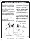
Check your water flow rate: A water flow of at least 3
gallons per minute is needed. A lower flow will keep your
softener from working as well as it should. Complete the
following steps to make an easy check of your flow rate.
1. Fully open two cold water faucets close to the point
water enters the house.
2. With both faucets open, fill a gallon container at one
faucet while looking at a watch or clock to see how
many seconds it takes.
3. Empty the container and go to the second faucet (be
sure BOTH faucets are still on). Fill the gallon container
at the second faucet and see how many seconds it
takes.
4. Turn off both faucets. Now add the number of seconds
it took to fill the container at both faucets.
5. A total of 90 seconds, or less, means the system flow
rate is good.
NOTE: Add these readings to the Facts and Figure
table on page 3.
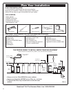
NOTE: Codes in the state of Massachusetts require
installation by a licensed plumber. For installation,
use plumbing code 248CMR of the Commonwealth
of Massachusetts.
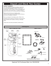
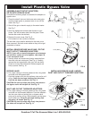
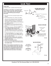
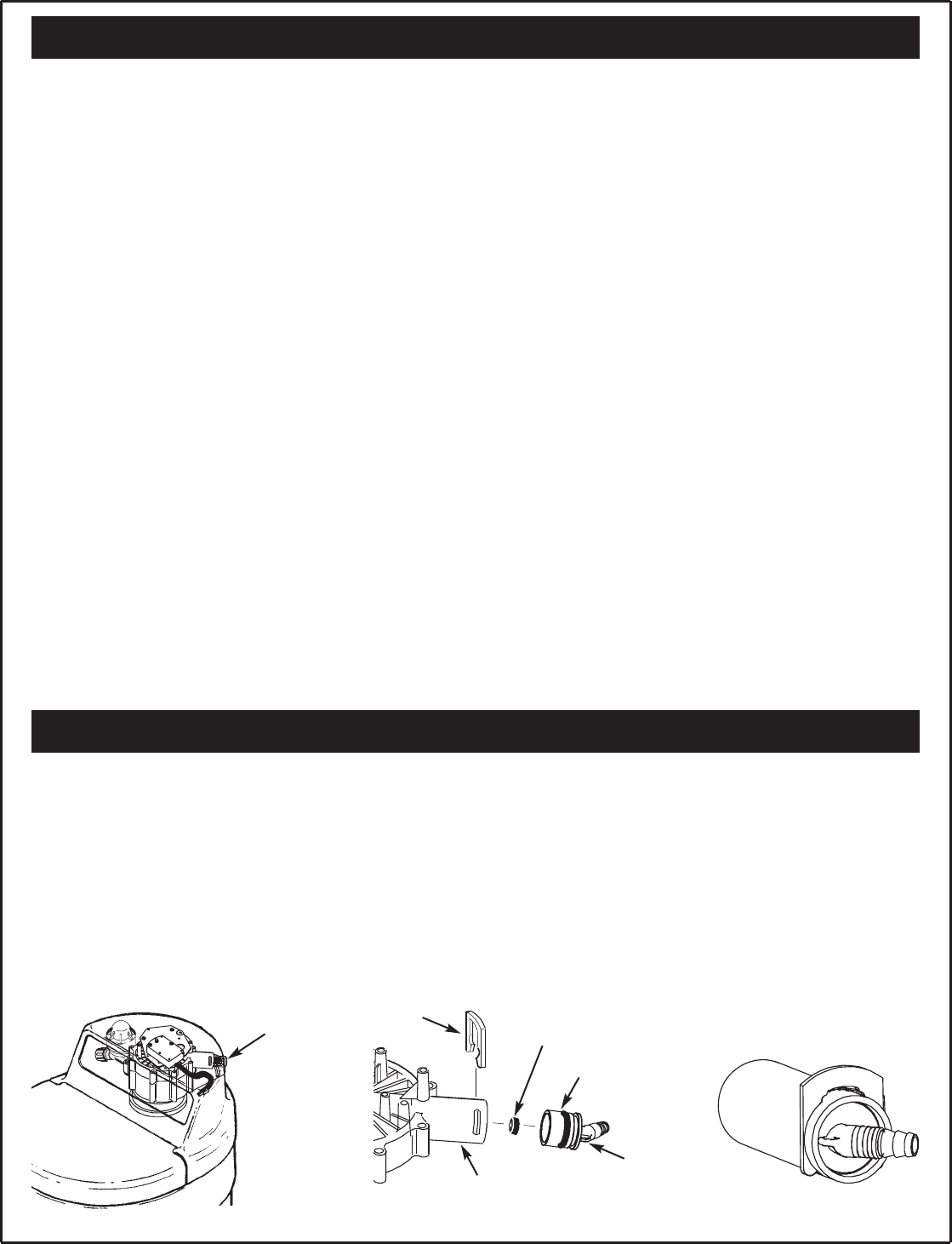
Remove
tube
Drain
elbow
Flow plug (should be
inside drain elbow)
Clip
O-ring
Drain port
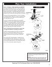
Assemble Drain Port Elbow
A disposable piece of tubing has been installed in the
“drain” port of your new water softener to protect it
during shipping. Please do the following:
1. Remove the tube from the valve (See Figure A).
2. Locate the drain elbow that is attached to the installa-
tion accessories cardboard display (See Figure B).
3. Make sure that the black O-ring is attached to the out-
side of the drain elbow. Also look inside the drain
elbow to be sure the small black flow plug is inside and
hasn’t fallen out during shipping.
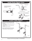
4. Insert the drain elbow into the valve’s “drain” port until
it stops and the black O-ring is pushed in beyond the
slots in the drain port with the smaller, barbed end
pointing out of the valve.
5. Secure the drain elbow to the valve using the black “U”
clip (also attached to the accessories cardboard dis-
play) by sliding it into the slots in the drain port and into
the grooves in the drain elbow (See Figure C).
6. Gently pull on the drain elbow to make sure it is secure
in the valve.
FIG. CFIG. A FIG. B