


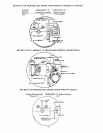
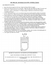

NOZZLES AND ELECTRODES: Use the proper size, spray angle, and spray pattern nozzle. Refer to the
recommended nozzle selection charts at the end of this manual. To install a nozzle, remove the nozzle line
electrode assembly, if necessary remove the retention ring assembly, and then install and tighten the nozzle.
Be careful not to damage the electrode insulators or the bend the electrode tips. After installing the nozzle,
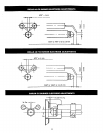
reassemble the nozzle line electrode assembly and set the electrode tip spacing. Depending on the bumer
purchased, the electrode tip spacing may need to be set prior to reassembling the nozzle line electrode
assembly. Refer to the figures on the following pages for setting the electrode tip spacing on Beckett, Carlin,
and Riello t_umers.
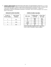
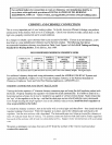
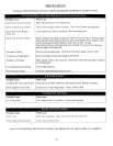
FINAL BURNER ADJUSTMENTS: Final burner adjustments must be made using combustion test
instruments. Initial settings for the burner are shown at the back of this manual.
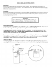
Set the burner accordingly. Check the draft over fire to verify that it is between M).01" WC and -0.02" WC,
otherwise adjust the draft as necessary. After operating 10 minutes to warm up the boiler, use the
combustion test equipment to take a smoke reading in the flue pipe between the boiler and the draft
regulator. The smoke reading should be zero to a trace (Shell Bacharach Scale). At times a new boiler
requires more than 10 minutes to burn clean due to the oil film on the new heat exchanger. If the smoke
reading is zero, gradually close the burner's air adjustment to obtain a smoke reading showing a trace smoke
reading. Once the smoke reading is a trace, measure the COz and as an insurance margin increase the air to
sufficiently reduce the CO2 by 1/2% to 1%.
Ira clean fire cannot be obtained, it will be necessary to verify the burner head and electrode alignment.
Proper electrode alignment figures are presented on the following pages. If the fire continues to be smoky,
replace the nozzle with a correct replacement.
Once the burner is completely adjusted, the burner should be started and stopped several times to assure
good operation with no fluttering or rumbling. Verify that there are no oil leaks and then record the nozzle
size, oil pressure, combustion readings, and air settings on a tag or label that can be attached to the burner or
boiler.
OIL BURNER MAINTENANCE: For the Becket/: AFG, Carlin EZ-1 or EZ-2, and the Riello 40 F3, F5, or
F10 the following preventative maintenance items should be performed annually, preferably prior to the
heating season.
1. Oil Burner Motor - For Beckett and Carlin burners, add 2 -3 drops of non-detergent electric motor oil
to each oil cup located at the front and rear of the motor (Riello burners are permanently lubricated).
Excessive oiling will shorten the life expectancy of the motor.
2. Fuel Filter - This should be replaced so as to prevent contaminated fuel from reaching the nozzle. A
partially blocked fuel filter can cause premature failure of the fuel pump.
3. Fuel Pump Unit - Replace pump screen and clean pump unit to maintain fuel delivery to the nozzle.
4. Ignition Electrodes - Clean and adjust as per manufacturer's recommendations, so as to maintain
reliable ignition of oil.
5. Nozzle - Replace so as to maintain safe and reliable combustion efficiency. Always replace with the
exact nozzle as required in the charts in the back of this manual.
6. Fan and Blower Housing These must be kept clean, free of dirt, lint and oil so as to maintain the
proper amount of air the fuel requires to burn.
7. Check the final burner adjustments.
I NOTE: If any component parts must be replaced, always I
i
use parts recommended by the burner manufacturer.
I
2l