


SYSTEM PIPING
I. When the installation of the boiler is for a new heating system, first instal! all of the radiation units
(panels, radiators, baseboard, or tubing) and the supply and return mains. After all heating system piping
and components have been installed, make final connection of the system piping to the boiler. It is
recommended to mount the circulating pump on the supply side piping, such that it pumps away from the
expansion tank. Refer to the figures on the next pages.
2. A hot water boiler installed above radiation level must be equipped with a low water cut off device. A
periodic inspection is necessary, as is flushing of float type devices, per low water cut off manufacturers
specific instructions.
.
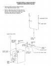
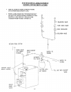
The packaged boiler unit is set up with 1-1/4" NPT supply and return piping from the front of the boiler.
The boiler supply and return piping can be moved to the rear of the boiler. The boiler should not be piped
return line to the front, supply line to the rear, or vice versa, as this will cause the boiler water to short
circuit the heat exchanger. Piping connections may require additional fittings and parts.
,
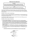
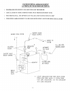
The relief valve is meant to be installed in the back side of the rear section using the 3/4" nipple and street
ell provided in the parts bag. Connect a discharge pipe of the same pipe size (3/4") to carry any water away
to a drain. Do not connect directly to a drain, but leave an air gap. No shutoffof any description shall be
placed between the safety relief valve and the boiler, or on discharge pipes between such safety valves and
the atmosphere. Installation on the safety relief valve shall conform to the ANSI/ASME Boiler and Pressure
Vessel Code, Section IV. The manufacturer is not responsible for any water damage.
5. When connecting the cold water supply to the pressure reducing valve, make sure that a clean water supply
is available. When the water supply is from a well or pump, a sand strainer should be installed at the pump.
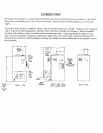
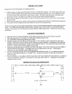
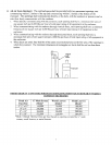
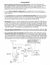
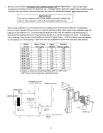
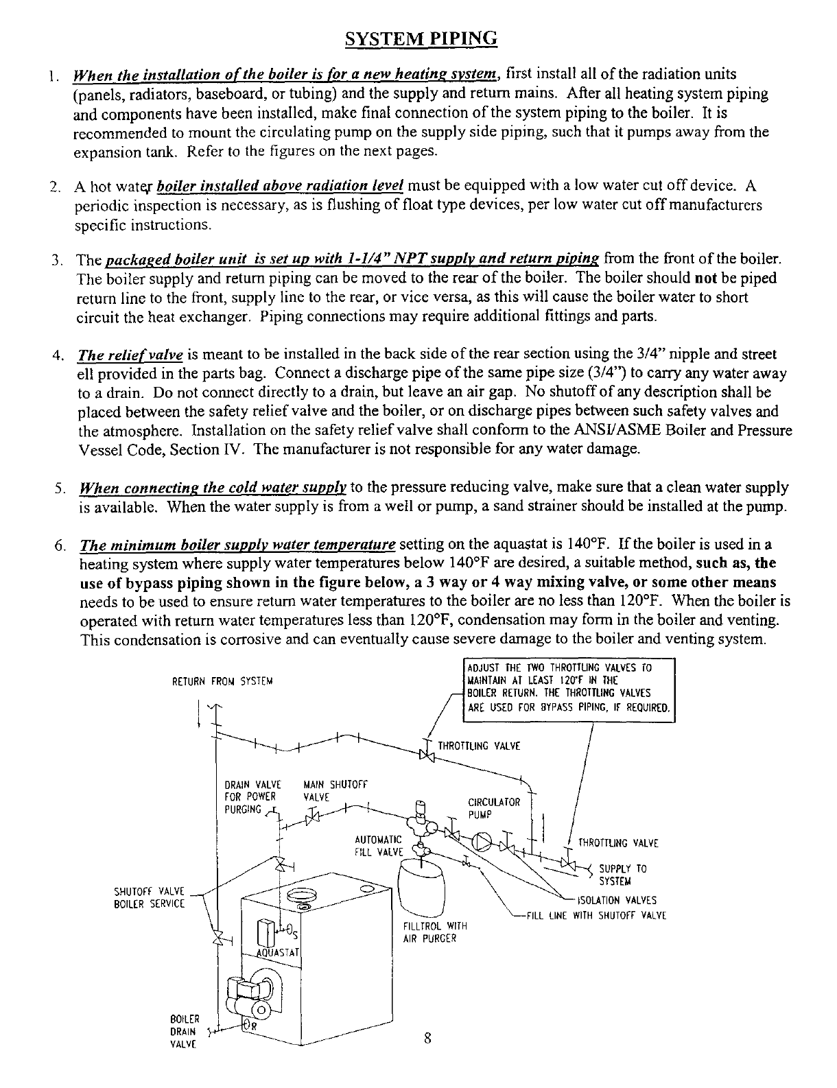
. The minimum boiler supply water temperature setting on the aquastat is 140°F. If the boiler is used in a
heating system where supply water temperatures below 140°F are desired, a suitable method, such as, the
use of bypass piping shown in the figure below, a 3 way or 4 way mixing valve, or some other means
needs to be used to ensure return water temperatures to the boiler are no less than 120°F. When the boiler is
operated with return water temperatures less than 120°F, condensation may form in the boiler and venting.
This condensation is corrosive and can eventually cause severe damage to the boiler and venting system.
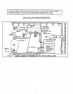
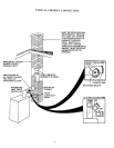
RETURN FROM SYSTEM
I
DRAINVALVE
FOR POWER
PURGING
SHUTOFF VALVE
BOILERSERVICE
MAIN SHUTOFF
VALVE
AUTOMATIC
FILL VALVE
i/_ADJUST THE TWOTHROTTLINGVALVESTO
MAINTAINAT LEAST12O'F IN THE
BOILERRETURN.THE THROTTLINGVALVES
ARE USED FOR BYPASSPIPING,IF REQUIRED.
THROTTLINGVALVE l
CIRCULATOR
PUMP l
OffUNG VALVE
SUPPLY TO
SYSTEM
ISOLATIONVALVES
_FILL LINEWITH SHUTOFFVALVE
FILLTROLWITH
AIR PURGER
BOILER
DRAIN
VALVE 8