


ELECTRICAL CONNECTIONS
Thermostat
Install a 24-volt thermostat (not provided) in a proper location. The location of the thermostat has an
important effect on boiler system operation. BE SURE TO FOLLOW THE INSTRUCTIONS INCLUDED
WITH THE THERMOSTAT.
Grounding
Permanently ground the boiler according to local codes and the National Electrical Code. Run a 14 gauge or
heavier copper wire from the boiler to a grounded connection in the service panel or a properly driven and
electrically grounded ground rod.
I
WARNING
Turn off electric power at fuse box before making any
line voltage connections. Follow local electrical codes.
I
Electric Power Supply
All electrical work must conform to your local codes as well as the National Electrical Code. If you are not
familiar with wiring and codes in general, have a competent electrician do this job.
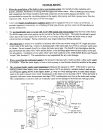
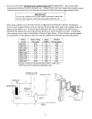
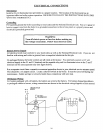
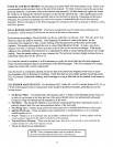
On packaged boilers, the boiler controls are all wired at the factory. You need only connect a 115 volt
electrical supply to the L1 and L2 terminals on the aquastat relay and two thermostat wires to the T and T
terminals on the same aquastat relay (see figure below).
Run a separate circuit from a separate overcurrent protection device in your electrical service entrance panel.
This should be a 15 ampere circuit. Locate a shut-off switch at the boiler. It must be turned offduring any
maintenance. Solder and tape or securely fasten these connections with wire nuts.
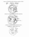
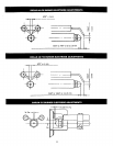
Oil Burner Wiring
For boilers packaged with oil burners, the burners are wired at the factory. For boilers shipped knockdown
or packaged without a burner, wiring connections are shown in the electrical wiring diagrams of this manua!.
115V 60 CYCLE
N H SUPPLY
It
,_24 VOLT
THERMOSTAT
II
AQUASTAT
RELAY
16