


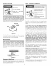
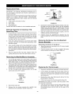

Testing the Igniter System
Turn off the gas to the water heater at the manual gas shut-off
valve. Watch the electrode tip while activating the igniter. A
visible spark should jump from the electrode. To avoid shock,
do not touch the burner or any metal part on the pilot or pilot
assembly. If no spark is visible, check the wire connections
and make sure the electrode is not broken. Replace the igniter
if defective. Dirt and rust on the pilot or electrode tip can
prevent the igniter spark. Wipe clean with a damp cloth and dry
completely. Rust can be removed from the electrode tip and
metal surfaces by lightly sanding with an emery cloth or fine
grit sandpaper.
Removing and Replacing the Gas Control
Valve/Thermostat
IMPORTANT: This water heater has a resettable thermal
switch installed. Do not attempt to disable or modify this
feature in any way. Use only factory authorized replacement
parts.
Removing the Gas Valve:
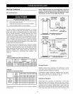
1. Turn off the gas supply to the water heater at the manual gas
shut-off valve. This valve is typically located beside the water
heater. Note the position of the shut-off valve in the open/on
position then proceed to turn it off (Figure 11).
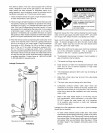
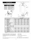
2. On the lower front of the water heater, locate the gas control
valve/thermostat (see Figure 32). Before performing any
maintenance, it is important to turn the temperature dial on
the gas control valve/thermostat to its lowest setting.
3. On top of the gas control valve/thermostat turn the gas
control knob to the "OFF" position. See Lighting Instructions
on the water heater.
4. Drain the water heater. Refer to the section of "Draining
and Flushing" section and follow the procedure.
5.
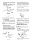
Disconnect the igniter wire from the igniter. NOTE: There are
two types of igniters. If you have the square igniter, slide the
igniter bracket backwards away from the gas valve to remove
it. If you have the round igniter, first remove the igniter from the
bracket by depressing front and rear holding tabs and lift. Next,
remove the igniter bracket from the gas valve. Disconnect the
thermocouple (right-hand threads), pilot tube, and manifold
tube at the gas control valve/thermostat (Figure 31). NOTE:
L.P. gas systems use reverse (left-hand) threads on the
manifold tube.
6.
Refer to "Gas Piping" section (Figure 11) and disconnect
the ground joint union in the gas piping. Disconnect the
remaining pipe from the gas control valve/thermostat.
To remove the gas control valve/thermostat, thread a
correctly sized pipe into the inlet and use it to turn the gas
control valve/thermostat (counterclockwise.) Do not use a
pipe wrench or equivalent to grip body. Damage may result,
causing leaks.
Do not insert any sharp objects into the inlet or outlet connections.
Damage to the gas control valve/thermostat may result.
Replacing the Gas Valve:
1. To replace the gas control valve/thermostat, reassemble
in reverse order. When replacing the gas control valve/
thermostat, thread a correctly sized pipe into the inlet and
use it to turn the gas valve (clockwise.) DO NOT OVER
TIGHTEN or damage may result. NOTE: Use an approved
TEFLON® tape or pipe compound only on the threaded
section of the gas control valve/thermostat that screws into
the tank.
2. Reconnect the gas piping to the gas control valve/
thermostat. NOTE: Use an approved Teflon tape or pipe
compound on the gas piping connections.
3. Attach the igniter and bracket to the new gas control valve/
thermostat, clipping it at the back edge of thermostat and
snapping it into place. NOTE: Do not use the (pilot) ferrule
nut supplied with the new gas control valve/thermostat,
unless the existing nut is not usable. Reconnect the pilot
tube, manifold tube, igniter wire, and thermal switch wires.
NOTE: L.R gas systems use reverse (left-hand) threads on
the manifold tube.
4. Fill the tank completely with water. NOTE: To purge the
lines of any excess air, keep the hot water faucet open for
3 minutes after a constant flow of water is obtained.
5. Turn on the gas supply and test the gas supply connections
by brushing on an approved noncorrosive leak detection
solution. Bubbles forming indicate a leak. Correct any leak
found.
6. Check the operation of the burner by following the lighting
instructions on the front of the water heater. With the
burner tit, check the gas control valve/thermostat supply
line, manifold tube and pilot tube connections for leaks.
7. Verify proper operation and then replace the outer door.
8. If additional information is required, contact Residential
Technical Assistance by referencing the number on the water
heater.
TEFLON ® is a registered trademark of E.I. Du Pont De Nemours
and Company.
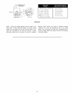
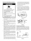
FVIR System Operational Checklist
1. Manifold gasket properly sealed.
2. Viewport not damaged or cracked.
3. Flame-arrestor free of debris and undamaged.
4. Two piece wire connector properly installed.
5. No leaks at pilot and manifold connection.
6. Manifold door screws securely tightened.
7. Depress the button on the thermal switch.
32