


Replacing the Manifold/Burner Assembly
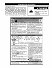
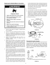
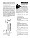
Explosion Hazard
Tighten both manifold door screws securely.
Remove any fiberglass between gasket
and combustion chamber.
Replace viewport if glass is missing or
damaged.
Replace two piece wire connector if missing or
removed.
• Replace door gasket if damaged.
• Failure to follow these instructions can result
in death, explosion, or fire.
7,
8.
9.
control valve/thermostat. Finally, start the thermocouple nut
and turn it all the way in by hand. An additional quarter turn
with a 3/8" open-end wrench will then be sufficient to seat
the lockwasher. When you are finished, connect the two
wire leads that go to the thermal switch.
Reconnect the igniter wire.
Turn gas supply on and refer to the Lighting Instructions.
With the burner tit, check the gas control valve/thermostat
supply line, two piece wire connector, manifold tube,
and pilot tube connections for leaks. Check for leaks by
brushing on an approved noncorrosive leak detection
solution. Bubbles forming indicate a leak. Correct any leak
found. IMPORTANT: All leaks must be fixed immediately.
10. Replace the outer door.
FLAMEARRESTOR BRACKET
1,
2.
3.
4,
5,
6,
Check the door gasket for damage or imbedded debris
prior to installation.
Inspect the view port for damage and replace as required.
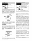
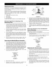
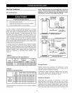
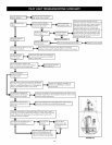
Insert the manifold/burner assembly into the burner
compartment, making sure that the tip of the manifold tube
engages in the slot of the bracket inside the combustion
chamber (Figures 39 & 40).
Inspect the door gasket and make sure there is no
fiberglass insulation between the gasket and the
combustion chamber.
Replace the two screws, which secure the manifold/
burner assembly door to the combustion chamber and
tighten securely. Once the manifold/burner assembly door
is tightened, visually inspect the door gasket between
the manifold/burner assembly door and the combustion
chamber for spaces or gaps that would prevent a seal.
IMPORTANT: Do not operate the water heater if the door
gasket does not create a seal between the manifold door
and the combustion chamber.
During the following procedure, do not cross-thread or
apply any thread sealant to any of the fittings listed below.
First, reconnect the manifold tubing to the gas control valve/
thermostat. NOTE: L.R gas systems use reverse (left-hand)
threads on the manifold tube.
NOTE: If a ferrule nut needs to be installed for the pilot
tube, locate the one provided with your parts kit. Install it in
the gas control valve/thermostat at the pilot location, hand
tight only.
Next, insert the pilot tube into the ferrule nut until it bottoms
out. NOTE: Hold the tube in this position. Tighten the ferrule
nut with a wrench until the crimp connection seals to the
pilot tube. Continue to tighten until the nut is tight in the gas
TiP
FIGURE 39.
TIP
MANIFOLD TUBE
CLOSE-UP INSIDE VIEW OF
THE COMBUSTION CHAMBER.
_ _SLOT
BRACKET
FIGURE 40.
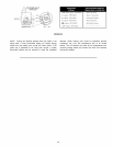
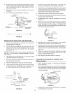
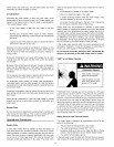
Piezoelectric Igniter System
The piezoelectric igniter system consists of the igniter button,
electrode, and wire. The pilot is ignited by an electric spark
generated when the igniter button is pressed. The spark gap
of 0.125 inch is set when the electrode is installed at the factory.
(Figure 41). Use only factory authorized piezoelectric igniter
parts for replacement.
__L IGNITER
BUTTON
%E
ECTRODE
SNAP-ON CONNECTOR
THERMOCOUPLE
/2PILOTI
BRACKET-_- ELECTRODE
* NOTE: SPARK GAP DISTANCE MEASURED FROM ELECTRODE TIP TO PILOT.
FIGURE 41.
31