


Installation Instructions (cont'd)
Gas Piping (cont'd)
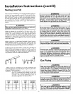
CORRECT GAS PIPE SIZE FOR
WATER HEATERS OPERATING ON NATURAL GAS
Basedon Inlet Gas Pressuresof 0.5 psigor Lessand
a Pressure Drop of 0.3 inchesWater Column.
(Basedon a 0.60 SpecificGravity Gas)
TOTAL INPUT*
BTU/HR
75,000
100,000
150,000
*Of all gas appliances
DISTANCE TO METER, IN FEET
20 30 60 90 125 150 200
'/2 3/4 3/, 3/, I I I
3/, 3/, 3/4 I I I I
3/, 3/4 t I 17, 17, 17,
l line.
A gas line of sufficient size must be run to the water heater.
Consult the latest edition of National Fuel Gas Code ANSI
Z223.1, also referred to as NFPA 54 and the gas company con-
ceming pipe size.
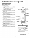
There must be:
• A readily accessible manu_i shut off valve in the gas supply line
serving the water heater, and
• A drip leg (sediment trap) ahead of the gas control valve to help
prevent dirt and foreign materials from entering the gas control
valve.
• A flexible gas connector or a ground oint union between the
shutoff valve and control valve to permit servicing of the unit.
Be sure to check all the gas piping for leaks before lighting the
water heater. Use a soapy water solution, not a match or open
flame. Rinse offsoapy solution and wipe dry.
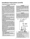
Standard Models are for installation up to 3,300 feet above sea
level.
High Altitude Models are for installation from 3,300 to 5,500 feet
above sea level.
Ifa standard model is installed above 3,300 feet or a high altitude
models is installed above 5,500 feet, the input rating must be
reduced at the rate of 4 percent for each 1,000 feet above sea level.
Contact your local Sears Service Center or gas utility for further
information.
AWARNING
The appliance and it_ must be leak tested
beforeplacingthe appliance in operation.
AWARNING
• The appliance and its individual shutoff valve must be discon-
nected from the gas supplypiping system during any pressure
testing of the gas system at test pressures in excess of
pound per square inch (3,5kPa).
• The appliance must be isolated from the gassupplypiping sys-
tem by closing its individual manual shutoff valve during any
pressuretesting of the gas supply piping system at test pres-
I
surfs equal or lessthan '/2pound per square inch (3.5kPa),
I
AWARNING
Use pipe joint compound or teflon tape marked as being
resistantto the actionof petroleum[Propane(I-E)] gases.
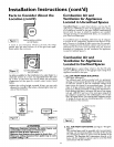
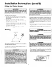
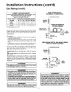
GAS PIPING WITH
FLEXIBLE CONNECTOR
MANUAL _GAS SUPPLYPIPING
SHUTOFF
VALVE
FLEXIBLE GAS CONNECTOR
LABELED AS COMPLYING
WITH ANSI STANDARDS
GROUNDJOIN ____
UNION (Optional)
3"_IN._ DRIP LEG
(Sediment trap)
I CAP
GAS
CONTROL
VALVE
GAS PIPING WITH ALL BLACK IRON
PIPE TO GAS CONTROL
" _ GASSUPPLYPIPING
I1
MANUAL _:_
SHUTOFF _l[_ I
VALVE _'_
BLACKPIPE
GROUND
JOINT U__
3" MIN.
_J CAP
GAS
CONTROL
VALVE
AWARNING
Contaminantsin the gaslinesmaycauseimproperoperation
of the gascontrol valvethat may result in fire or explosion.
Beforeattachingthe gaslinebe surethat all gaspipeisclean
on the inside.To trap anydirt or foreignmaterial in the gas
supplyline, a drip leg (sometimes calleda sediment trap)
must be incorporated in the piping. The drip leg must be
readily accessible.Installinaccordancewith the "Gas Piping"
section.Referto the latest editionof the NationalFuel Gas
Code,ANSI Z223.1, also referred to as NFPA54.
16