


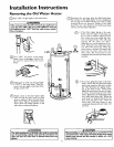
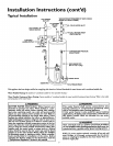

Installation Instructions (cont'd)
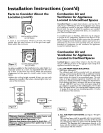
Combustion Air and
Ventilation for Appliances
Located in Confined Spaces (cont'd)
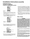
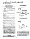
Figure 7 ]
ALT I_LETAIR VENTILATIONLOOVERS
1. When directly communicating with the outdoors, each open-
ing shall have a minimum free area of 1 square inch per 4,000
BTU per hour of total input rating of all equipment in the
enclosure. (See Figure 7.)
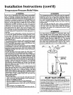
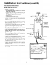
2. When communicating with the outdoors through vertical
ducts, each opening shall have a minimum free area of 1
square inch per 4,000 _TU per hour of total input rating of
all equipment in the enclosure. (See Figure 8.)
Figure 8 ]
_CHIMNEY OR GAS VENT
VENTILATION LOUVERS
(each end c4att_)
TLET
WATER HEATER
FURNACE
IN L'EI AIR OUCT
• a_ov e floorI
I I I
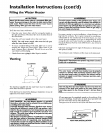
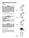
3. When communicating with the outdoors through horizontal
ducts, each opening shall have a minimum free area of 1
square inch per 2,000 BTU per hour of total input rating of
all equipment in the enclosure. (See Figure 9.)
Figure 9 ]
CHIMNEY OR GAS VENT
_ OUTLet AIR DUCT
-- INLET Afft DUCT
: .=...•-.- -.-•-.- ]
4. When ducts are used, they shall be of the same cross-sectional
area as the flee area of the openings to which they connect.
The minimum short side dimension of rectangular air ducts
shall not be less than 3 inches. (See Figure 9.)
5. Louvers and Grilles: In calculating free area, consideration
shall be given to the blocking effect of louvers, grilles or
screens protecting openings. Screens used shall not he smaller
than ¼ inch mesh. If the free area through a design of louver
or grille is known, it should be used in calculating the size
opening required to provide the free area specified. If the
design and free area is not known, it may be assumed that
wood louvers will be 20-25 percent free area and metal louvers
and grilles will have 60-75 percent free area. Louvers and
grilles shah be fixed in the open position or interlocked with
the equipment so that they are opened automatically during
equipment operation.
6. Special Conditions Created by Mechanical Exhausting or
Fireplaces: Operation of exhaust fans, ventilation systems
clomes dryers or fireplaces may create conditions requiring
special attention to avoid unsatisfactory operation of installed
gas utilization equipment.
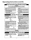
Water Piping
_WARNING
HOTTER WATER CAN SCALD: Water heaters are intended to
>reducehot water. Water heated to a temperature which will
satisfy'clotheswashing, dishwashing, and other sanitizing needs
can scald and permanently injure you upon contact. Some peo-
)le are more likelyto be permanently injured by hot water than
others. These includethe elderly,children,the infirm, or pbysical-
ly/mentally handicapped. If anyoneusinghot water in your home
fitsinto one of these groupsor ifthere is a localcodeor state law
requiring a certain temperature water at the hot water tap, then
_u must take specialprecautions. In addition to usingthe lowest
)ossibletemperature setting that satisfies your hot water needs,
a means suchas a mixing valve, shouldbe used at the hot water
taps usedby these people or at the water heater. Mixing valves
are availableat plumbing supplyor hardware stores.Followman-
ufacturers instructions for installation of the valves, Before
changing the factory setting on the thermostat, read the
"Temperature Regulation" sectionin this manual.
This water heater shall not be connected to any heating systems
or component(s) used with a non-potable water heating
appliance.
lfa water heater is installed in a closed water supply system; such as
one having a back-flow preventer, check valve, water meter with a
check valve,etc.., in the cold water supply; means shall be provided
to control thermal expansion. Contact the local utility or local Sears
ServiceCenter on how to control this situation.
NOTE: To _protect against untimely corrosion of hot and
cold water fittings, it is strongly recommended that di-elec-
tric unions or couplings be installed on this water heater
when connected to copper pipe.
NOTE: If using copper tubing, solder tubing to an adapter
before attaching the adaptor to the cold water inlet connection,
Do not solder the cold water supply line dlrecdy to the cold
water inlet. It will harm the dip tube and damage the tank.
12