


Installation Instructions (cont'd)
Gas Piping
_,WARNING
Make sure the gassuppliedisthe same type listedon the
model rating plate.The inlet gaspressuremust not exceed
10.5in,water column(2.6kPa)for naturalgasor 13in.water
column (3.2kPa) for propane(L.R) gas.The minimum inlet
gaspressurelistedon the model rating plate isfor the pur-
poseofinputadjustment.
&WARNING , ]
Ifthe gascontrolvalveissubjectedto pressuresexceeding'/2I
poundper squareinch(3.5kPa),the damageto the gascon-I
trol valvecouldresult inafire or explosionfromleakinggas. J
_,WARNING
If the main gaslineshutoffservingall gasappliancesisused,
alsoturn "off" the gasat eachappliance. Leaveall gasappli-
ancesshutoffuntilthe water heaterinstallationiscomplete.
_,WARNING ]
Use pipe joint comp_ape marked as being|
resistant to theactionofpetroleum[Propane(LP.)] gases, j
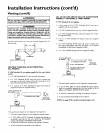
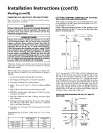
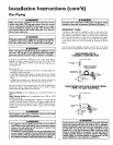
SEDIMENT TRAP
A sediment trap shall be installed as close to the inlet of the
water heater as practical at the time of water heater installation.
The sediment trap shall be either a tee fitting with a capped nip-
ple in the bottom outlet or other device recognized as an effec-
tive sediment trap. Ira tee fitting is used, it shall be installed in
conformance with one of the methods of installation shown
below.
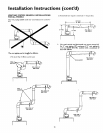
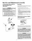
Connecting the gas piping to the gas control valve of the water
heater can be accomplished by either of the two methods shown.
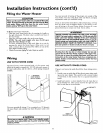
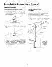
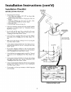
GAS PIPING WITH
FLEXIBLE CONNECTOR
A gas line of suft]cient size _nust be run to the water heater.
Consult the latest edition of National Fuel Gas Code ANSI
Z223.1, also referred to as NFPA 54 and the gas company con-
cerning pipe size.
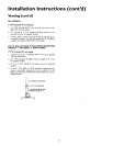
There must be:
• A readily accessible manual shut off valve in the gas supply line
serving the water heater, and
• A drip leg (sediment trap) ahead of the gas control valve to help
prevent dirt and foreign materials from entering the gas control
valve,
• A flexible gas connector or a ground joint union between the
shutoffvalve and control valve to permit servicing of the unit.
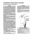
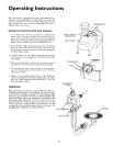
Be sure to check all the gas piping for leaks before lighting the
water heater. Use a soapy water solution, not a match or open
flame. Rinse offsoapy solution and wipe dry.
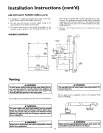
Standard Models are for installation up to 3,300 feet above sea
level.
High Altitude Models are for installation from 3,300 to 5,500
feet above sea level.
If a standard model is installed above 3,300 feet or a high altitude
model is installed above 5,500 feet, the input rating must be
reduced at the rate of 4 percent for each 1,000 feet above sea level.
Contact your local Sears Service Center or gas utility for further
information.
&WARNING
The appliance and its gasconnection must be leak tested
beforeplacingthe applianceinoperation.
AWARNING
• The appliance and its individualshutoff valve must be discon-
nected from the gasSupplypiping systemduring any pressure
testing of the gas system at test pressures in excess of I/2
pound per square inch(3.5kPa).
• The appliance must be isolatedfrom the gassupplypipingsys-
tem by closing its individual manual shutoff valve during any
pressure testing of the gas supply piping system at test pres-
suresequal or lessthan I/2 pound per square inch(3.5kPa).
22
MANUAL SHUT OFFVALVE _AS SUPPLY PIHNG
FLEXIBLEGAS CONNECTOR
LABELED AS COMPLYING
WITH ANSI STANDARDS
LOOP
GROUND }OIN_
UNION (OprJonal)
3" MIN.
GAS
CONTROL
VALVE
GAS PIPING WITH ALL BLACK IRON
PIPE TO GAS CONTROL
MANUAL SHUT OFF _CA$ SUPPLY PIPING
VALVE
BLACK PIPE
GROUND JOINT
UNION
3" MIN.
GAS
CONTROL
VALVE
&WARNING
Contaminants in the gas lines may cause improper operation
of the gas control valve that may result in fire or explosion.
Before attaching the gas line be sure that all gaspipe isclean
on the inside. To trap any dirt or foreign material in the gas
supply line, a drip leg (sometimes called a sediment trap)
must be incorporated in the piping. The drip leg must be
readily accessible.Install in accordance with the "Gas Piping"
section. Refer to the latest edition of the National Fuel Gas
Cede, ANSI Z223.1, also referred to asNFPA 54.