


Installation Instructions (cont'd)
AWARNING
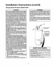
A gaswater heater cannot operate properly without the cor-
rect amount of air for combustion. Do not install in a con-
fined area such a closet, unless you provide air as shown in
the "Locating The New Water Heater" section. Never
obstruct the flow of ventilation air If you have any doubts or
questions at all, call your gascompany. Failure to provide the
proper amount of combustion air can result in a fire or explo-
sion and can cause DEATH, SERIOUS BODILY INJURY, OR
PROPERTY DAMAGE.
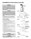
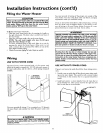
9"min. from
any overhang
-_. of Flue
12" min.
r
_iWARNING
If this water heater will be used in beauty shops,barber shops,
cleaning establishments, or self-service laundries with dry
cleaning equipment, it is imperative that the water heater or
water heaters be installed so that combustion and ventilation
air be taken from outside these areas. Refer to the "Locating
The New Water Heater" section of this manual and also the
latest edition of the National Fuel Gas Cede, ANSI Z223.1, also
referred to as NFPA 54 for specificsprovided concerning air
required.
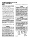
Combustion Air and Ventilation
When determining the installation location for apower vent
water heater, snow accumulation and drifting shouldbe consid-
ered in areas where applicable.
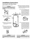
VENTING CLEARANCES
• 0" clearance for Y (or optional 2") PVC, ABS or CPVC Schedule
40 vent piping from combustible surfaces,
• 12" minimum from the ground, 9" ceiling overhangs. Figure 2.
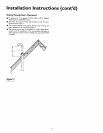
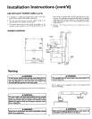
• The Power Vent outlet terminal shall terminate at least 36" above
any forced air inlet located within 10 feet. Figure3a.
• The Power Vent outlet terminal shall terminate at least 9" below, 9"
horizontally from or 9" above any door, window or gravity air inlet
into the building. Figure 3a.
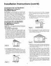
• 18" minimum in all directions from any obstruction that may
interfere. Figure 3b.
• 18" minimum from other gravity or natural appliance outlet vents
when directly above or 135° to either side of center line. Figure 3c.
• 36" minimum from any outlet vents when directly below or 45° to
either side of center line. Figure3c.
• 36" minimum in all directions from any other forced air appliance
outlet vent. Figure 3c.
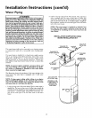
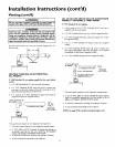
• The location selection must provide clearances for servicing and
proper operation of the water heater. Figure 4.
• Vent termination must not be within 4 feet of any items such as gas
meters, gas valves or other gas regulating equipment.
• The venting system must be installed in a manner which allows
inspection of the installation of the venting pipes and joints as well
as periodic inspection after installation as required by ANSI
Standards.
li WARNING
Ventterminationmustnotbewithin4 feetofanyitemssuchas
gasmeters,gasvalvesor othergasregulating equipment,
li WARNING
Failureto haverequired clearancesbetweenwater heaterand
combustiblematerialwillresult ina firehazard.
10
Figure 2 ]
LESSTHAN
120"
TERMINAL 12" rain.
FORCED AIR
INLET
IFigure 3a 1
Figure 3b]
f VENT TERMINAL
_18" MIN. _
i
IE" TO WALL OR OTHER
OBSTRUCTIONS THAT
MAY INTERFERE WITH
VENTING,
VENT TERMINAL
:ORNER OF BUILDING
jf _ *THIS DIMENSION I$
POWER VENT TERMINAL _ • "_ INCREASED TO 36"WHEN
-- - _ --, THE VENT OUTLET ISFOR A
-- _ ,RCED VENT APPLIANCE
- DIRECT VENT OR
GRAVITY VENTED
APPLIANCE
.__ ---36" " _!
-ANY OTHER OUTLET VENT
[F,gur c]
Must maintain
adequate service
and maintenance L
_i_i'_i__ ,,,
_cces$i_ili_
F_,_ .,-_ -_-_,
I L _ ril_'r '
i Figure 4 I availableforvent
pipe ins=llation.