


17
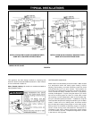
Connecting the gas piping to the gas control valve of the water
heater can be accomplished by either of the two methods shown in
Figures 15 and 16.
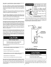
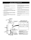
SEDIMENT TRAPS
A sediment trap shall be installed as close to the inlet of the water
heater as practical at the time of water heater installation. The
sediment trap shall be either a tee fi tting with a capped nipple in the
bottom outlet or other device recognized as an effective sediment
trap. If a tee fi tting is used, it shall be installed in conformance with
one of the methods of installation shown in Figures 15, 16 and 17.
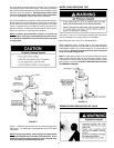
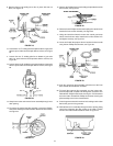
FIGURE 15. GAS PIPING WITH FLEXIBLE CONNECTOR.
FIGURE 16. GAS PIPING WITH ALL
BLACK IRON PIPE TO GAS CONTROL.
ALTERNATIVE SEDIMENT TRAP LOCATION
FIGURE 17.
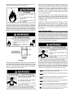
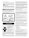
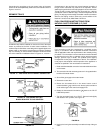
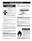
Contaminants in the gas lines may cause improper operation of
the gas control valve that may result in fi re or explosion. Before
attaching the gas line be sure that all gas pipe is clean on the inside.
To trap any dirt or foreign material in the gas supply line, a drip leg
(sometimes called a sediment trap) must be incorporated in the
piping. The drip leg must be readily accessible. Install in accordance
with the “Gas Piping” section. Refer to the current edition of the
National Fuel Gas Code, ANSI Z223.1/NFPA 54.
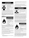
FUEL CONVERSION INSTRUCTIONS FROM
NATURAL GAS TO PROPANE (L.P.) GAS
Fuel conversions shall be completed by a qualified service
agency in accordance with the detailed conversion instructions
and all applicable codes and requirements of the authority having
jurisdiction. The information in these instructions must be followed
to minimize the risk of fi re or explosion and to prevent property
damage, personal injury or death. The qualifi ed service agency
is responsible for the proper installation of this kit. The installation
is not proper and complete until the operation of the appliance is
checked as specifi ed in the manufacturer’s instructions.
1. Read and follow detailed conversion instructions below and also
on the heater.
2. The conversion kit with necessary parts are in a bag attached to
the side of the water heater.
3. Shut off the gas supply to the water heater.
4. Remove the outer door.
5. Rotate the thermostat dial on the water heater control
counterclockwise (
) until the main burner ignites and burns
off all residual gas in the control and supply lines.
6. Rotate the thermostat dial clockwise (
) back to the “PILOT
LIGHTING” position.
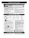
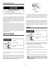
7. Turn the gas control knob “A” to “PILOT”. Depress knob slightly
and rotate to “OFF” position, see Figure 18.
FIGURE 18.
8. Unplug wire from igniter assembly mounted to the top of the gas
valve.