


Removing and Replacing the Gas Control
Valve/Thermostat
IMPORTANT: The gas control valve/thermostat is a standard
valve with a right-hand thread thermocouple. Use only factory
authorized replacement parts.
Removing the Gas Control Valve/Thermostat:
1. Turn the gas control knob on the combination gas control
valve/thermostat clockwise to the "OFF" position. NOTE:
Depress the dial stop on Robertshaw valves before turning
the gas control knob. See Lighting Instructions on the water
heater.
2. Turn off the gas at the manual shut-off valve on the gas
supply pipe (Figure 3).
3. Drain the water heater. Refer to "Draining" section and
follow the procedure.
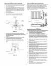
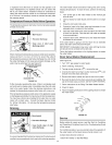
4. Disconnect the igniter wire from the igniter. NOTE: First
remove the igniter from the bracket by depressing front
and rear holding tabs and lift. Next remove igniter bracket
from the gas control valve/thermostat. Disconnect the
thermocoupte (right-hand threads), pilot tube, and manifold
tube at the gas control valve/thermostat (Figure 25).
5. Refer to "Gas Piping" section and disconnect the ground
joint union in the gas piping. Disconnect the remaining
pipe from the gas control valve/thermostat.
6. To remove the gas control valve/thermostat, thread a
correctly sized pipe into the inlet and use it to turn the gas
control valve/thermostat (counterclockwise.) Do not use
pipe wrench or equivalent to grip body. Damage may
result, causing leaks. Do not insert any sharp objects into
the inlet or outlet connections. Damage to the gas control
valve/thermostat may result.
Replacing the Gas Control Valve/Thermostat:
To replace the gas control valve/thermostat, reassemble
in reverse order. When replacing the gas control valve/
thermostat, thread a correctly sized pipe into the inlet and use
it to turn the gas control valve/thermostat (clockwise. DO NOT
OVER TIGHTEN, damage may result.
• Be sure to use approved Teflon®tape or pipe joint
compound on the gas piping connections and fitting on
the back of the gas control valve that screws into tank.
• Be sure to remove the pilot ferrule nut from the new gas
control valve/thermostat.
• Turn the gas supply on and check for leaks. Test all
connections by brushing on an approved noncorrosive
leak-detection solution. Bubbles will show a leak. Correct
any leak found.
• Be sure tank is completely filled with water before lighting
and activating the water heater. Follow the "Operating
Instructions"
• If additional information is required, contact Sears Service
at: 1-800-4-MY-HOME ®(1-800-469-4663).
®
TEFLON is a registeredtrademarkof E.I.Du Pont De Nemours and Company.
Housekeeping
Vacuum around base of water heater for dust, dirt, and lint on
a regular basis.
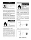
Fire and Explosion Hazard
• DO not obstruct _mbustion air
o_nings at the bottom of the
water heater.
Do not use or store fl_ammable
vapor products such as gasoline,
solvents or adhesives in the
_me room or area near water
heater or other appliance,
• Visibly inspect _ame arrestor at
least on_ every six months and
clean ifaccumu_a_d Hnto
• Can cause serious injury or
death,
AT LEAST ONCE EVERY SiX MONTHS A VISUAL
INSPECTION SHOULD BE MADE OF THE FLAME
ARRESTOR. CLEAN IF LINT ACCUMULATIONS ARE
NOTICED.
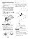
INSTALLED IN SUITABLE AREA: To insure sufficient ventilation
and combustion air supply, proper clearances from the water
heater must be maintained. See Facts to Consider About the
Location section. Combustible materials such as clothing,
cleaning materials, or flammable liquids, etc. must not be placed
against or adjacent to the water heater because they could
catch on fire.
Anode Rod Inspection
Property Damage Hazard
- Avoid water heater damage.
• Inspection and replacement of anode rod required.
The anode rod is used to protect the tank from corrosion. Most
hot water tanks are equipped with an anode rod. The submerged
rod deteriorates to protect the tank. Instead of corroding the tank,
water ions attack and eat away the anode rod. This does not
affect the water's taste or color. The rod must be maintained to
keep the tank in operating condition.
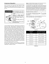
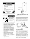
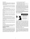
EXPOSED \\
SUPPORT _ - _,_",tr_ _ . _,_ _7£"_...,,,_,.J1_1=,_,_
WIRE\ "__t'l'_'# _i'l lll_ " _'_ _ _ #_'_ _ ¢__
_\ \\ ....... \\ 't
LilIIIIII_"_'_ __ _,_'_t_EXPOSED
I IIIIIII1_ ',_''_'a,',['J_ = _l,_'%,,_ ,t_.,t_. _" _' SUPPORT
PITTED ANODE ROD----------------" WIRE
FIGURE 32
Anode deterioration depends on water conductivity, not
necessarily water condition. A corroded or pitted anode rod
indicates high water conductivity and should be checked and/
24