


• DoobtainnewwarningandinstructionlabelsfromSearsfor
placementontheblanketdirectlyovertheexistinglabels.
• Doinspecttheinsulationblanketfrequentlytomakecertain
itdoesnotsag,therebyobstructingcombustionairflow.
Combustion Air and Ventilation for
Appliances Located in Unconfined Spaces
UNCONFINED SPACE is space whose volume is not tess than
50 cubic feet per 1,000 Btu per hour (4.8 m3 per kW) of the
aggregate input rating of all appliances installed in that space.
Rooms communicating directly with the space in which the
appliances are installed, through openings not furnished with
doors, are considered a part of the unconfined space.
In unconfined spaces in buildings, infiltration may be adequate
to provide air for combustion, ventilation and dilution of flue
gases. However, in buildings of tight construction (for example,
weather stripping, heavily insulated, caulked, vapor barrier,
etc.), additional air may need to be provided using the methods
described in Combustion Air and Ventilation for Appliances
Located in Confined Spaces.
Combustion Air and Ventilation for
Appliances Located in Confined Spaces
CONFINED SPACE is a space whose volume is tess than
50 cubic feet per 1,000 Btu per hour (4.8 m3per kW) of the
aggregate input rating of all appliances installed in that space.
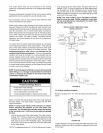
A. ALL AIR FROM INSIDE BUILDINGS:
(See Figure 9 on page 10 and Figure 10 below)
The confined space shall be provided with two permanent
openings communicating directly with an additional room(s) of
sufficient volume so that the combined volume of all spaces
meets the criteria for an unconfined space. The total input of all
gas utilization equipment installed in the combined space shall
be considered in making this determination. Each opening shall
have a minimum free area of one square inch per 1,000 Btu per
hour (22 cm2/kW) of the total input rating of all gas utilization
equipment in the confined space, but not tess than 100 square
inches (645 cm2). One opening shall commence within 12 inches
(30 cm) of the top and one commencing within 12 inches (30
cm) of the bottom of the enclosures.
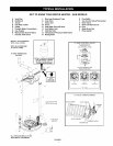
CHIMNEY OR GAS VENT
FURNA R OPENINGS
[ ! I_! [--! i I" [_!
l [ 1 ! [ ! 1 _ 1 1
F t IJ J I-_1 ILIZr
FIGURE 10.
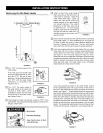
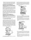
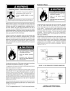
B. ALL AIR FROM OUTDOORS: (See Figures 9, 11,12,13 and 13A)
The confined space shall be provided with two permanent
openings, one commencing within 12 inches (30 cm) of the top
and one commencing within 12 inches (30 cm)from the bottom
of the enclosure. The openings shall communicate directly, or
by ducts, with the outdoors or spaces (crawl or attic) that freely
communicate with the outdoors.
CHIMNEY OR
GAS VENT
VENTILATION LOUVERS
END OF ATTIC)
OUTLETAIR
WATER HEATER
FURNACE
INLET MR DUCT
ALT. INLETAIR VENTILATION LOUVERS
FIGURE 11.
When directly communicating with the outdoors, each opening
shall have aminimum free area of 1 square inch per 4,000 Btu
per hour (5.5 cm2/kW) of total input rating of all equipment in
the enclosure. See Figure 11.
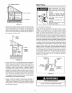
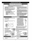
When communicating with the outdoors through vertical
ducts, each opening shall have a minimum free area of
1 square inch per 4,000 BTU per hour (5.5 cm2/kW) of
total input rating of all equipment in the enclosure. See
Figure 12.
VENTILATION LOUVERS
OF ATTIC)
WATER HEATER
• FURNACE
INLET AIR DUCT
(ENDS 1' OR 30 cm
_ _:_, ' r' , , , L_! ABOVEFLOOR)
171 1 •
FIGURE 12.
• When communicating with the outdoors through horizontal
ducts, each opening shall have a minimum free area of
1 square inch per 2,000 BTU per hour (11 cm2/kW) of
total input rating of all equipment in the enclosure. See
Figure 13.
• When ducts are used, they shall be of the same cross-
sectional area as the free area of the openings to which
they connect. The minimum short side dimension of
rectangular air ducts shall not be less than 3 inches
(76.2 mm). See Figure 13.
11