


Installation Instructions (cont'd)
A, WARNING
• Theapplianceand itsindividualshutoffvalvemust:bediscon-
nectedfromthe gassupplypipingsystemduringanypressure
testingof the gassystemat test pressuresin excessof
poundpersquareinch(3.5kPa).
• Theappliancemust beisolatedfromthegassupplypipingsys
tem byclosingitsindividualmanualshutoffvalveduringany
pressuretestingofthe gassupplypipingsystemat test pres-
suresequalorlessthan½poundper squareinch(3.5kPa).
li WARNING
Use pipe joint compound or teflon tape marked as being
resistant to the actionofpetroleum[Propane(L.R)]gases.
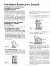
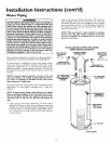
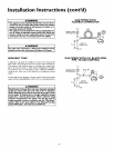
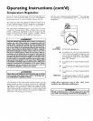
GAS PIPING WITH
FLEXIBLE CONNECTOR
O,OO OO T
UNlON(Opti_ VE
CAP
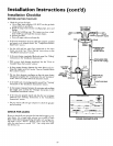
SEDIMENT TRAP
A sediment trap shall be installed as close to the inlet of the
water heater as practical at the time of water heater installation.
The sediment trap shall be either a tee fitting with acapped nip-
ple in the bottom outlet or other device recognized as an effec-
tive sediment trap. If a tee fitting is used, it shall be installed in
conformance with one of the methods of installation shown
below.
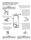
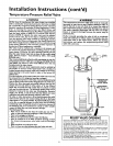
Connecting the gas piping to the gas control valve of the water
heater can be accomplished by either of the two methods shown,
li WARNING
Contaminantsinthe gaslinesmaycauseimproperoperation
of the gascontrolvalvethat may resultin Ere or explosion.
Beforeattachingthe gaslinebe surethat allgaspipeisclean
on the inside.To trap any dirt orforeign material in the gas
supplyline, a drip leg (sometimes called a sedimenttrap)
must be incorporated in the piping.The drip leg must be
readily accessible.Installinaccordancewith the "Gas Piping"
section.Referto the latesteditionof the National FuelGas
Code,ANSI Z223.1,alsoreferred to asNFPA 54.
GAS PIPING WITH ALL BLACK IRON
PIPE TO GAS CONTROL
GROUND JOINT _ BLACK PIPE
UNION(Optional) __
GAS
CONTROL
VALVE
15