17
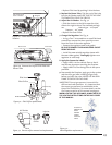
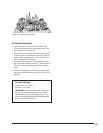
• Replace Pilot Hood by pushing it into the base.
5. Replace the Burner Tube:. Slip the end of the tube
into the Air Shutter and SLIDE TUBE TO THE RIGHT
TO COMPLETELY COVER THE ORIFICE.
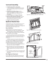
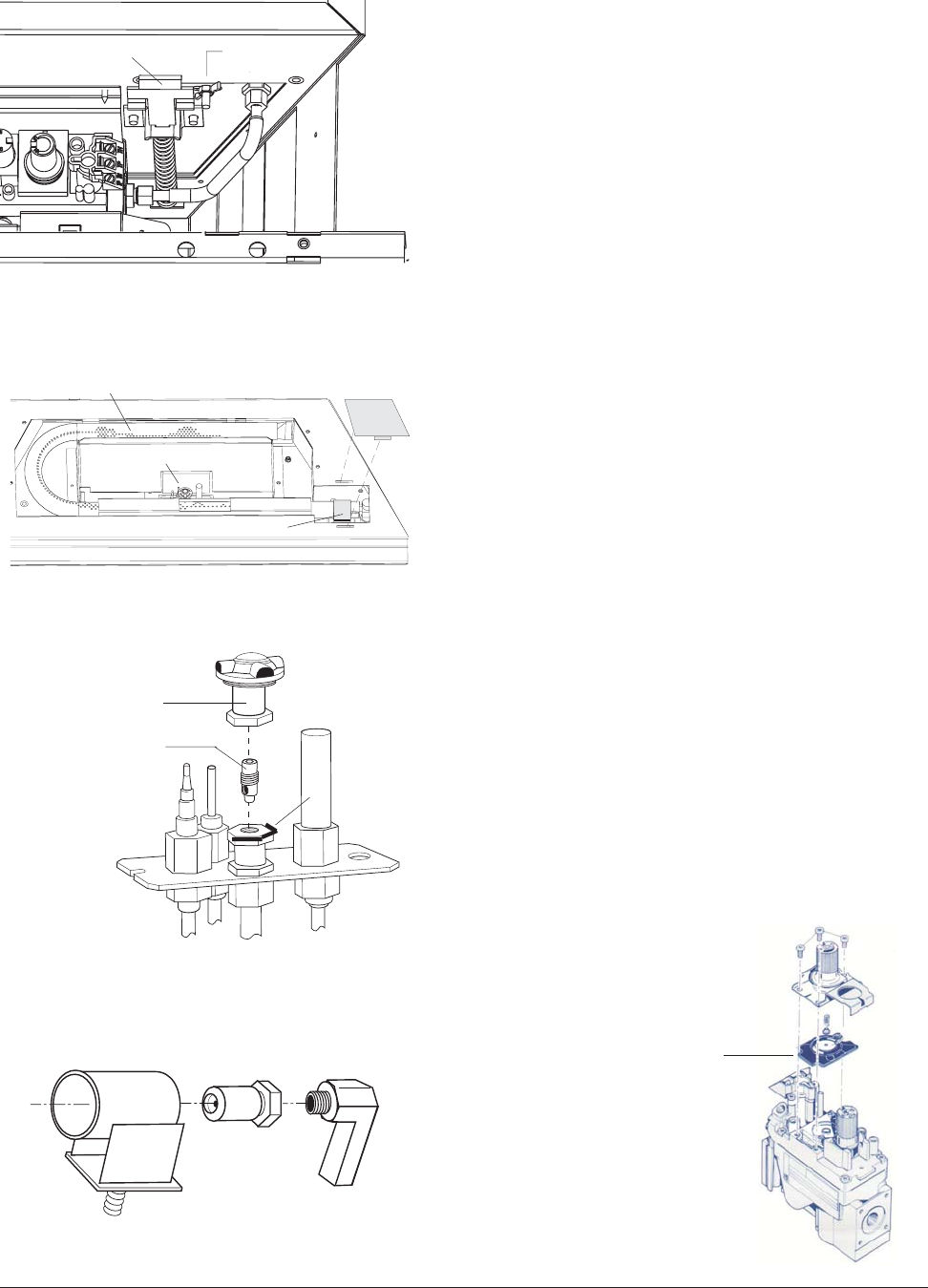
6. Adjust the Air Shutter: See Fig. 31.
• Slide the shutter to the left to open the inlet,
slide to the right to close. The standard settings
are: Natural gas - 1/4” open
Propane - 1/2” open
• Replace the Cover Plate.
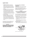
7. Change the Regulator: See Fig. 32.
• Using a Torx T-20 screwdriver or small flat head
screwdriver, remove the three specialty screws
from the front of the valve regulator.
• Remove the regulator tower and gasket.
BE SURE TO REMOVE THE BLACK RUBBER GASKET
FROM THE VALVE.
• Install the new variable regulator tower with
the new rubber gasket. Thoroughly tighten new
regulator to valve body.
8. Apply the Conversion Labels:
• Apply LABEL A to the cabinet floor so that it
may be seen by anyone servicing the fireplace.
• Apply LABEL B to the Rating Plate in the space
provided.
9. Reassemble the fireplace, apply gas to the system
and check for gas leaks including all gas lines
before and after the valve. NEVER USE AN OPEN
FLAME TO CHECK FOR GAS LEAKS.
IMPORTANT: Correct gas pressure is essential for
efficient and safe operation. It is important that
the correct gas pressure be established at the
time of the installation. For more details, see the
Gas Pressure section of this manual on page 12.
WHEN LIGHTING THIS APPLIANCE, ALWAYS REFER TO
THE LIGHTING INSTRUCTIONS ON THE BACK COVER
OF THIS MANUAL.
BE SURE TO
REMOVE THE
BLACK
RUBBER
GASKET
FROM THE
VALVE.
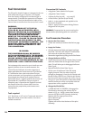
Figure 32.
Valve Regulator replacement.
Figure 31. Burner orifice removal and replacement.
Injector
Air Shutter
Stem
Burner
Orifice
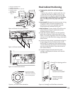
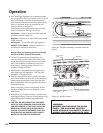
Figure 28. Frame latch and air shutter stem
location.
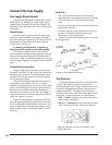
Figure 29. Remove the Orifice Cover Plate and
Burner Tube.
Air Shutter
Wingnut
Pull Frame Spring
Latch to release.
Pilot Assembly
Cover Plate
Burner Tube
Air Shutter
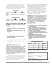
Figure 30. Pilot Orifice replacement.
PILOT ASSEMBLY
Pilot Hood
Pilot Orifice
Retainer Clip


