15
The appliance must be isolated from the gas
supply line by closing its individual manual gas
shutoff valve (gas cock) during any pressure testing
of the gas supply piping system that is equal to or
exceeds pressures of 1/2 psig (3.5 kPa).
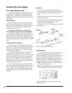
Inlet Pressure
MIN MAX
Natural Gas: 5.0 WC (1.24 kPa) 7.0 WC (1.74
kPa)
Propane: 11.0 WC (2.73 kPa) 13.0 WC (3.23
kPa)
Manifold Pressure
MIN MAX
Natural Gas: 1.6 WC (.39 kPa) 3.5 WC (.87 kPa)
Propane: 6.4 WC (1.59 kPa) 10.0 WC (2.48 kPa)
ALWAYS TEST PRESSURE WITH VALVE CONTROL KNOB
SET ON HIGH. Symptoms of incorrect gas pressure
include:
Insufficient gas pressure:
• Small pilot flame which can result in insufficient
millivolts.
• Little variation in flame picture between HI and
LO settings.
• Insufficient gas to support more than one appli-
ance causing nuisance outages or gas surges.
Excessive gas pressure:
• Permanent damage to valve causing complete
appliance shut down.
• Too large a pilot flame resulting in overheating of
the power generator and consequent shut down.
• Sooting due to impingement and/or incorrect fuel
to air mix.
High Altitude Adjustment
Installations located at altitudes from 2000 - 4500 ft.
(610 M - 1370 M), require compensation for the
thinner air (less volume of air per cubic foot). Higher
altitudes affect the atmospheric pressure and heat
value of gaseous fuels. The lower oxygen content in
the air and the lower gas viscosity require the use of
a different orifice to achieve efficient, clean combus-
tion at the burner tube.
For high altitude installations consult the local
gas distributor or the authority having jurisdiction
for proper rating methods. If the installer must
convert the unit to adjust for varying altitudes, use
Jøtul High Altitude Kit (#137403).
In the U.S: THE DERATING KIT MUST BE INSTALLED BY
AN AUTHORIZED SERVICE TECHNICIAN IN ACCOR-
DANCE WITH THE MANUFACTURER’S INSTRUCTIONS
AND ALL CODES AND REQUIREMENTS OF THE
AUTHORITY HAVING JURISDICTION. THE INFORMA-
TION STICKER MUST BE COMPLETED BY THE IN-
STALLER AND APPLIED TO THE APPLIANCE AT THE
TIME OF THE CONVERSION. THE QUALIFIED SERVICE
AGENCY PERFORMING THIS WORK ASSUMES RE-
SPONSIBILITY FOR THIS DERATING.
In Canada: This unit has been tested for installation
at high altitudes in accordance with Canadian test
standard CAN/CGA-2.17. THE DERATING SHALL BE
CARRIED OUT IN ACCORDANCE WITH THE REQUIRE-
MENTS OF THE PROVINCIAL AUTHORITIES HAVING
JURISDICTION AND IN ACCORDANCE WITH THE
REQUIREMENTS OF THE CAN1-B-149.1 AND .2
INSTALLATION CODE.
Derating Procedure
1. Follow Steps 1-4 of the Fuel Conversion procedure
outlined on page 14.
2. Remove the original orifice. Consult Table 1 to
determine the correct orifice size for your eleva-
tion and fuel type. Install the appropriate orifice
included in the high altitude kit.
3. Fill out the high altitude conversion label and
attach to the rating plate or fireplace cabinet floor
See Figure 27.
4. Reassemble the firebox components.
5. It may be necessary to adjust the air shutter on
the burner tube. See the AIR SHUTTER/FLAME
APPEARANCE section of this manual for more
details.
Table 1. High Altitude Orifice Chart.
Figure 27. High Altitude Conversion Label.
THIS STOVE HAS BEEN CONVERTED FOR USE AT AN
ALTITUDE OF: ________________
Orifice Size: ____________ Manifold Press. _____
Input Btu/Hr. ___________ Fuel Type __________
Date of Conversion ___________
High Altitude Orifice Chart
Elevation Fuel
0 - 2000 ft. Natural Gas #37 220018
(0 - 610 m) Propane 1.55 mm 220048
2001 - 4500 ft. Natural Gas #38 129130
(611 - 1370 m) Propane 1.50 mm 129146
Orifice
Size
Part No.


