


368262-UIM-B-1008
8 Johnson Controls Unitary Products
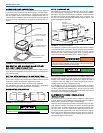
FURNACE ASSEMBLY - MC & FC SERIES COILS
These coils are factory shipped for installation in either upflow or down-
flow applications with no conversion.
Position the coil casing over or under the furnace opening as shown in
Figure 8 after configuring coil flanges as required see “Coil Flange” sec-
tion below.
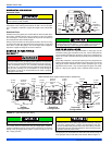
COIL FLANGE INSTALLATION
The coils include removable flanges to allow proper fit up with furnaces
having various inlet and outlet flange configurations. The two flanges
are attached to the top of the coil in the factory during production. For
proper configuration of flanges refer to Figure 9.
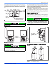
FURNACE ASSEMBLY - MC SERIES COILS ONLY
MC coils are supplied ready to be installed in a horizontal position. A
horizontal pan is factory installed. MC coils should be installed in all hor-
izontal applications with the horizontal drain pan side down.
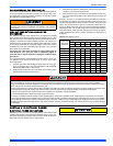
For horizontal left hand applications no conversion is required to an MC
coil when used with a downflow/horizontal furnace. A mounting plate,
supplied with every coil should always be installed on the side desig-
nated as top side. See Figures 10 & 11.
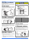
FURNACE ASSEMBLY - PC SERIES COILS
These upflow coils are designed for installation on top of upflow fur-
naces only.
If the coil is used with a furnace of a different size, use a 45° transition
to allow proper air distribution through the coil.
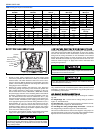
1. Position the coil casing over the furnace opening as shown in Fig-
ure 12.
2. Place the ductwork over the coil casing flange and secure.
3. Check for air leakage between the furnace and coil casing and
seal appropriately.
NOTE: Dimension “C” should be at least 2/3 of dimension “D”. See Fig-
ure 12.
CRITICAL COIL PROJECTION
The coil assembly must be located in the duct such that a minimum dis-
tance is maintained between the top of the coil and the top of the duct.
Refer to Table 2.
COIL / FURNACE ASSEMBLY - HC SERIES COILS
These coils are supplied ready to be installed in a right hand position or
a left hand position. When used in conjunction with a horizontal furnace
(blow through) application, the coil should be oriented with the opening
of the “A” coil closest to the furnace. See Figure 13.
NOTE: Each coil is shipped with an external tie plate that should be
used to secure the coil to the furnace. It should be installed on the back
side of the coil using the dimpled pilot holes. See Figure 13.
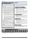
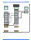
FIGURE 9: Coil Flange
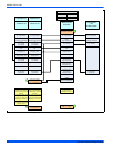
FIGURE 10: Horizontal Right Application (Typical)
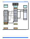
FIGURE 11: Horizontal Left Application
ALTERNATE
FLANGE LOCATION
(Used fordownflow or
horizontal left
installations)
FACTORY
FLANGE
LOCATION
(Used forupflow
or horizontal
right installations)
Furnace
Mounting Plate
Furnace
Mounting Plate
Do not drill any holes or drive any screws into the front duct
flange on the coil in order to prevent damaging coil tubing. See
Figure 12.
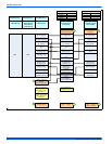
FIGURE 12: PC Series Upflow Coil Installation
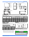
Table 2: Coil Projection Dimensions - PC Series Coils
COIL SIZE DIMENSION “C” INCH
PC18 3-1/2
PC24 4-1/2
PC30, PC32, PC35 4-1/2
PC42, PC43, PC36, PC37 5-1/2
PC48 6-1/2
PC60 9
FIGURE 13: Horizontal Left or Right application (Right Shown)
Flexible
Duct Collar
Do not drill
or Screw
this flange
Field
Fabricated
Ductwork
Upflow
Coil
Upflow
Furnace
Secondary
Drain
Primary
Drain
D
C
(Min)
Alternate
Drain Location
Use tie plate
supplied with coil
Air flow
Gas Furnace