


368262-UIM-B-1008
Johnson Controls Unitary Products 13
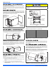
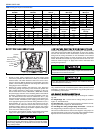
For additional connection diagrams for all UPG equipment refer to “Low Voltage System Wiring” document available online at www.upgnet.com in the
Product Catalog Section.
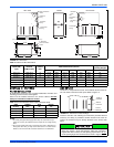
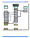
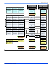
FIGURE 19: Thermostat Chart - Single Stage Air Conditioner – Variable Speed or PSC Modulating Furnace
HM1
Humidistat
Y
Full Stage Compressor
G
Fan
*PP11C70224
THERMOSTAT
RH
24 – Volt Hot
(Heat XFMR)
RC
24 – Volt Hot
(Cool XFMR)
W
Full Stage Heat
Clipping Jumper W914 for
electric heat on thermostat
is not necessary
C
24 – Volt Common
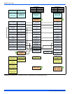
Y
Compressor
SINGLE STAGE
AIR CONDITIONER
Y
Compressor Contactor
SINGLE STAGE
AIR
CONDITIONER
C
24 – Volt Common
R
24 – Volt Hot
Y1
Single
Stage Compressor
MODULATING
FURNACE CONTROL
G
Fan
MODULATING
FURNACE
Y/Y2
Second or Full
Stage Compressor
DHUM
Dehumidification-
Open on Humidity Rise
W
Modulating Heat
Part Numbers:
SAP = Legacy
1
1
Move HUMIDISTAT
jumper to “YES”
if humidistat is to be used.
ID MODELS
LO COMP
Single Stage
Compressor (OUT)
O
Reversing Valve
Energized in Cool
HI COMP
Second Stage
Compressor (OUT)
Part Number:
S1-2HU16700124
2
External Humidistat
(Optional)
Open on Humidity Rise
2
TP(8,L)C
YP(8,L)C
CP(8,L)C
LP(8,L)C