


368262-UIM-B-1008
26 Johnson Controls Unitary Products
ADJUSTMENT OF FAN CONTROL SETTINGS
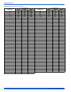
Cooling - The airflow delivered by the furnace during cooling operation
can be adjusted to match the cooling capacity of the A/C condensing
unit. This is done by moving the COOL and ADJ jumper on the control
board to give the desired airflow.
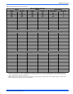
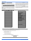
The COOL jumper has four positions, which will deliver sufficient airflow
in cooling mode for the cooling capacities shown in Table 13.
the ADJ jumper has three positions which can be used to make further
adjustments to the cooling blower airflow.
Continuous Fan Operation - The airflow delivered by the furnace dur-
ing continuous fan operation can be adjusted as desired. This is done
my moving the control fan jumper on the control board to give the
desired airflow.
The jumper has three positions. The "H" position delivers maximum air-
flow, 100% of the blower capacity. Position "M" delivers approximately
70% of the blower capacity. And Position "L" delivers minimum airflow,
approximately 40% of the blower capacity.
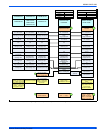
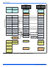
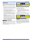
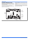
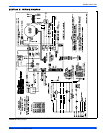
FIGURE 29: Furnace Control Board
EAC
Terminals
Humidifier
Terminals
Cooling
Speed
Jumper
Heat Pump
Jumper
Zoning
Jumper
Humidistat
Jumper
Continuous
Fan Speed
Jumper
Test
Button
Low
Voltage
Terminals
Last
Error
Button
Diagnostic
Light