


697936-UIM-B-01211
Johnson Controls Unitary Products 37
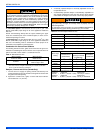
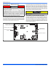
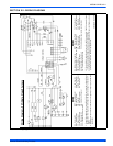
SECTION XII: WIRING DIAGRAM
FIGURE 41: Wiring Diagram
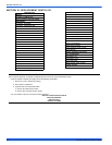
LEGEND
DSͲDoorswitch MOTͲCirculatingmotor LSͲLimitswitch
ROSͲRolloutswitch IDMͲInducermotor HUMͲHumidifier
FSͲFlamesensor CAPͲCapacitor XFMRͲTransformer
TSTͲWallthermostat HSIͲHotsurfaceigniter GVͲGasvalve
PS1ͲPressureswitch EACͲElectronicaircleaner
PS2–Condensatepressureswitch
1.Ifanyof
theoriginalwireassuppliedwiththefurnacemustbereplaced,itmust
bereplacedwithwiringmaterialhavingatemperatureratingofatleast221ȚF
(105C).
2.Blowermotorspeedconnectionsshownaretypical,butmayvarybymodeland
application.
LEGENDE
DSͲCommutateurdeporte MOTͲMoteursoufflerie TSTͲThermostat
ROSͲCommutateurderoulement IDMͲD’inductmoteur FSͲCapteurdeflame
XFMRͲTransformeur GVͲSoupapedegaz CAPͲCapaciteur
LSͲCommutateurdelimite HUMͲHumidificateur EACͲFiltreélectrique
HSIͲIgnitiondesurfacechaud PS2ͲCommutateurdepression,condensation
PS1ͲCommutateurdepression
1.Sil'undesfilsd'originefourniaveccefourdoitêtreremplacé,ildoitêtreremplacéavec
lefilayantundegrédetempératured'aumoins221ȚF(105C).
2.Lesconnexionsàgrandevitessedumoteurduventilateurindiquéssonttypiques,mais
peuventvarierselonlemodèleetparapplication.
WiringDiagram
–
95%SingleͲStageX Furnace
501025-UWD-C-0810