


697936-UIM-B-01211
Johnson Controls Unitary Products 33
NOTES:
1. Airflow expressed in standard cubic feet per minute (CFM).
2. Motor voltage at 115 V.
SECTION IX: SAFETY CONTROLS
CONTROL CIRCUIT FUSE
A 3-amp fuse is provided on the control circuit board to protect the 24-
volt transformer from overload caused by control circuit wiring errors.
This is an ATO 3, automotive type fuse and is located on the control
board.
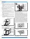
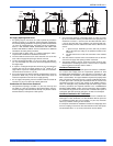
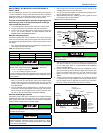
BLOWER DOOR SAFETY SWITCH
This unit is equipped with an electrical interlock switch mounted in the
burner compartment. This switch interrupts all power at the unit when
the panel covering the blower compartment is removed.
Electrical supply to this unit is dependent upon the panel that covers the
blower compartment being in place and properly positioned.
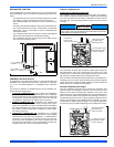
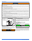
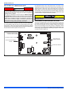
ROLLOUT SWITCH CONTROLS
These controls are mounted on the burner assembly. If the temperature
in the area surrounding burner exceeds its set point, the gas valve is
de-energized. The operation of this control indicates a malfunction in
the combustion air blower, heat exchanger or a blocked vent pipe con-
nection. Corrective action is required. These are manual reset controls
that must be reset before operation can continue.
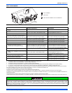
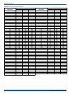
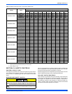
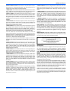
Table 17: Blower Performance CFM - Any Position (without filter)
Models Speed
Bottom Airflow Data (SCFM)
Ext. Static Pressure (in. H2O)
0.1 0.2 0.3 0.4 0.5 0.6 0.7 0.8 0.9 1.0
TM9X040A10MP11
High 1290 1260 1220 1160 1100 1040 960 840 750 660
Medium High 1170 1140 1110 1070 1040 990 930 820 730 650
Medium 990 980 940 900 860 830 790 730 680 630
Medium Low 900 880 850 810 770 730 670 630 600 560
Low 730 710 690 650 620 590 540 510 480 450
TM9X060B12MP11
High 1402 1374 1354 1328 1299 1262 1222 1167 1107 1036
Medium High 1252 1233 1203 1182 1150 1125 1095 1064 1031 980
Medium 1076 1059 1029 1007 973 946 908 883 843 800
Medium Low 988 967 936 903 875 838 806 765 737 685
Low 798 769 727 695 650 619 574 517 485 443
TM9X080B12MP11
High 1445 1423 1397 1365 1339 1311 1283 1250 1204 1140
Medium High 1282 1266 1232 1211 1182 1157 1128 1097 1069 1013
Medium 1098 1084 1059 1027 998 967 939 910 879 822
Medium Low 1012 993 953 930 894 851 828 773 752 692
Low 865 810 763 730 689 628 594 520 496 448
TM9X080C16MP11
High 1713 1682 1643 1600 1558 1519 1480 1436 1385 1333
Medium High 1554 1519 1485 1439 1404 1368 1327 1280 1176 1130
Medium 1380 1351 1302 1263 1224 1171 1128 1085 1030 943
Medium Low 1177 1142 1083 1050 988 922 890 819 798 687
Low 951 841 650 588 457 418 355 227 203 N / A
TM9X100C16MP11
High 1734 1694 1650 1611 1570 1536 1485 1438 1392 1335
Medium High 1568 1537 1492 1453 1414 1373 1327 1279 1230 1118
Medium 1420 1380 1332 1294 1249 1196 1152 1100 981 938
Medium 1218 1169 1124 1067 1015 965 894 845 754 679
Low 979 846 647 580 464 427 345 220 195 N / A
TM9X100C20MP11
High 2143 2102 2065 2028 1989 1944 1892 1825 1733 1625
Medium High 1788 1749 1718 1672 1629 1587 1541 1500 1447 1355
Medium 1575 1539 1500 1456 1410 1363 1305 1246 1095 1030
Medium Low 1372 1325 1276 1225 1170 1111 1044 972 884 812
Low 1031 921 810 728 660 615 518 474 391 355
TM9X120D20MP11
High 2214 2173 2132 2086 2036 1994 1952 1907 1849 1777
Medium High 1841 1799 1749 1699 1659 1611 1567 1520 1471 1372
Medium 1605 1562 1514 1470 1416 1361 1310 1180 1119 1045
Medium Low 1405 1362 1303 1244 1189 1125 1054 986 876 826
Low 1135 1020 844 758 671 557 511 464 387 N / A
Main power to the unit must still be interrupted at the main power dis-
connect switch before any service or repair work is to be done to the
unit. Do not rely upon the interlock switch as a main power discon-
nect.
Blower and burner must never be operated without the blower panel
in place.