


697936-UIM-B-01211
Johnson Controls Unitary Products 15
ACCESSORY CONNECTIONS
The furnace control will allow power-switching control of various acces-
sories.
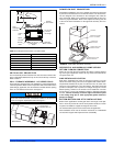
ELECTRONIC AIR CLEANER CONNECTION
Two 1/4” (6.4 mm) spade terminals (EAC and NEUTRAL) for electronic
air cleaner connections are located on the control board. The terminals
provide 115 VAC (1.0 amp maximum) during circulating blower opera-
tion.
HUMIDIFIER CONNECTION
Two 1/4” (6.4 mm) spade terminals (HUM and NEUTRAL) for humidifier
connections are located on the control board. The terminals provide 115
VAC (1.0 amp maximum) during heating system operation.
A mounting hole is provided on the control panel next to the furnace
control board for mounting a humidifier transformer if required.
TWINNING
These furnaces are not to be twinned. If more than one furnace is
needed in an application, each furnace must have its own complete
duct system and its own wall thermostat.
SECTION VI: CONDENSATE PIPING AND
FURNACE VENTING CONFIGURATION
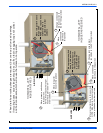
CONDENSATE DRAIN LOCATION
As shipped from the factory:
• For all 040, 060 & 080K input furnaces the main drain is plumbed
through the casing right-side opening when viewed from the front
of the furnace.
• For all 100 & 120 input furnaces the main drain is plumbed through
the casing left-side opening when viewed from the front of the fur-
nace.
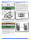
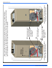
The condensate hoses must slope downwards at all points.
When drain hose routing changes are required (shown in Figures 22-
25), be sure to cap all un-used openings.
If rerouting hoses - excess length should be cut off so that no sagging
loops will collect and hold condensate - which will cause the furnace to
not operate.
No hose clamps are needed for connecting to the condensate pan.
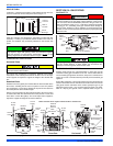
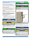
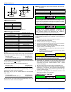
The condensate will flow to the drain better if an open stand pipe is
installed in the drain line. See Figure 20.
If evaporator coil or humidifier drains are combined with the furnace
drain, then the open stand pipe could be raised higher, above the 5”
minimum.
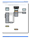
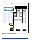
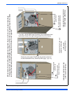
The Figures 22 - 25 show the condensate drain arrangement for the
various possible furnace and vent blower positions.
The furnace condensate pan is self priming and contains an internal
trap to prevent flue gas leaking. Do not install an external condensate
trap.
The furnace, evaporator coil, and humidifier drains may be combined
and drained together. The evaporator coil drain may have an exter-
nal, field-supplied trap prior to the furnace drain connection to prevent
conditioned air leakage. All drain connections (furnace, evaporator
coil, or humidifier) must be terminated into an open or vented drain as
close to the respective equipment as possible. Regular maintenance
is required on condensate drainage system.
NOTICE
Condensate must be disposed of properly. Follow local plumbing
or wastewater codes. The drain line must maintain a 1/4" per foot (20
mm/m) downward slope to the drain.
If an external vent tee is being installed, then it must have its own
condensate trap before it is disposed into an open or vented drain.
This is not to be considered as a second trap as referenced else-
where in this document.
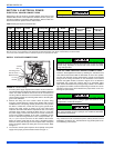
FIGURE 20: Typical. Condensate drain, vertical installation
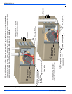
A loop has been added to the pressure switch vacuum hose. How-
ever, ensure that all pressure switch hoses are routed such that they
prevent any condensate from entering the pressure switch.
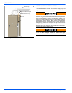
It is possible for condensation to form inside the combustion air
(intake) pipe in the summer months if significant length of combustion
air pipe passes through conditioned space. This problem can be
averted by the addition of a simple drain tee, or a drain tee with a
drain on the combustion air pipe as close to the furnace as possible,
as shown in Figure 21. This is true for all long horizontal venting in
any furnace configuration. This will prevent the condensate from
entering the furnace.
To Open Or
Vented Drain
Tee
5” Min.
Open Stand Pipe
(Anti-siphon air vent)
NOTICE