


438335-UIM-B-0509
Johnson Controls Unitary Products 9
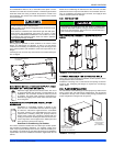
HORIZONTAL APPLICATION
Horizontal Filters
Any branch duct (rectangular or round duct) attached to the plenum
must attach to the vertical plenum before the filter. The use of straps
and/or supports is required to support the weight of the external filter
box.
Downflow Filters
Downflow furnaces typically are installed with the filters located above
the furnace, extending into the return air plenum or duct. Any branch
duct (rectangular or round duct) attached to the plenum must attach to
the vertical plenum above the filter height.
Filter(s) may be located in the duct system external to the furnace using
an external duct filter box attached to the furnace plenum or at the end
of the duct in a return filter grille(s). The use of straps and/or supports is
required to support the weight of the external filter box.
SECTION IV: GAS PIPING
GAS SAFETY
GAS PIPING INSTALLATION
Properly sized wrought iron, approved flexible or steel pipe must be
used when making gas connections to the unit. If local codes allow the
use of a flexible gas appliance connection, always use a new listed con-
nector. Do not use a connector that has previously serviced another gas
appliance.
Some utility companies or local codes require pipe sizes larger than the
minimum sizes listed in these instructions and in the codes. The furnace
rating plate and the instructions in this section specify the type of gas
approved for this furnace - only use those approved gases. The instal-
lation of a drip leg and ground union is required. Refer to Figures 15.
The furnace must be isolated from the gas supply piping system by
closing its individual external manual shutoff valve during any pressure
testing of the gas supply piping system at pressures equal to or less
than 0.5 psig (3.5 kPa).
Gas piping may be connected from either side of the furnace using any
of the gas pipe entry knockouts on both sides of the furnace. Refer to
Figures 12.
GAS ORIFICE CONVERSION FOR PROPANE (LP)
This furnace is constructed at the factory for natural gas-fired operation,
but may be converted to operate on propane (LP) gas by using a
factory-supplied LP conversion kit. Follow the instructions supplied with
the LP kit.
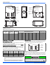
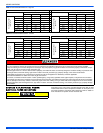
HIGH ALTITUDE GAS ORIFICE CONVERSION
This furnace is constructed at the factory for natural gas-fired operation
at 0 –5,000 feet (0 – 1,524 m) above sea level.
The manifold pressure must be changed in order to maintain proper
and safe operation when the furnace is installed in a location where the
altitude is greater than 5,000 feet (1,524 m) above sea level. Refer to
Table 5 for proper manifold pressure settings.
HIGH ALTITUDE PRESSURE SWITCH CONVERSION
For installation where the altitude is less than 5,000 feet (1,524m), it is
not required that the pressure switch be changed unless you are in an
area subject to low pressure inversions.
All filters and mounting provision must be field supplied. All installa-
tions must have a filter installed.
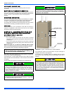
An overpressure protection device, such as a pressure regulator,
must be installed in the gas piping system upstream of the furnace
and must act to limit the downstream pressure to the gas valve so it
does not exceed 0.5 psig [14" w.c. (3.48 kPa)]. Pressures exceed-
ing 0.5 psig [14” w.c. (3.48 kPa)] at the gas valve will cause damage
to the gas valve, resulting in a fire or explosion or cause damage to
the furnace or some of its components that will result in property
damage and loss of life.
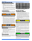
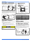
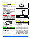
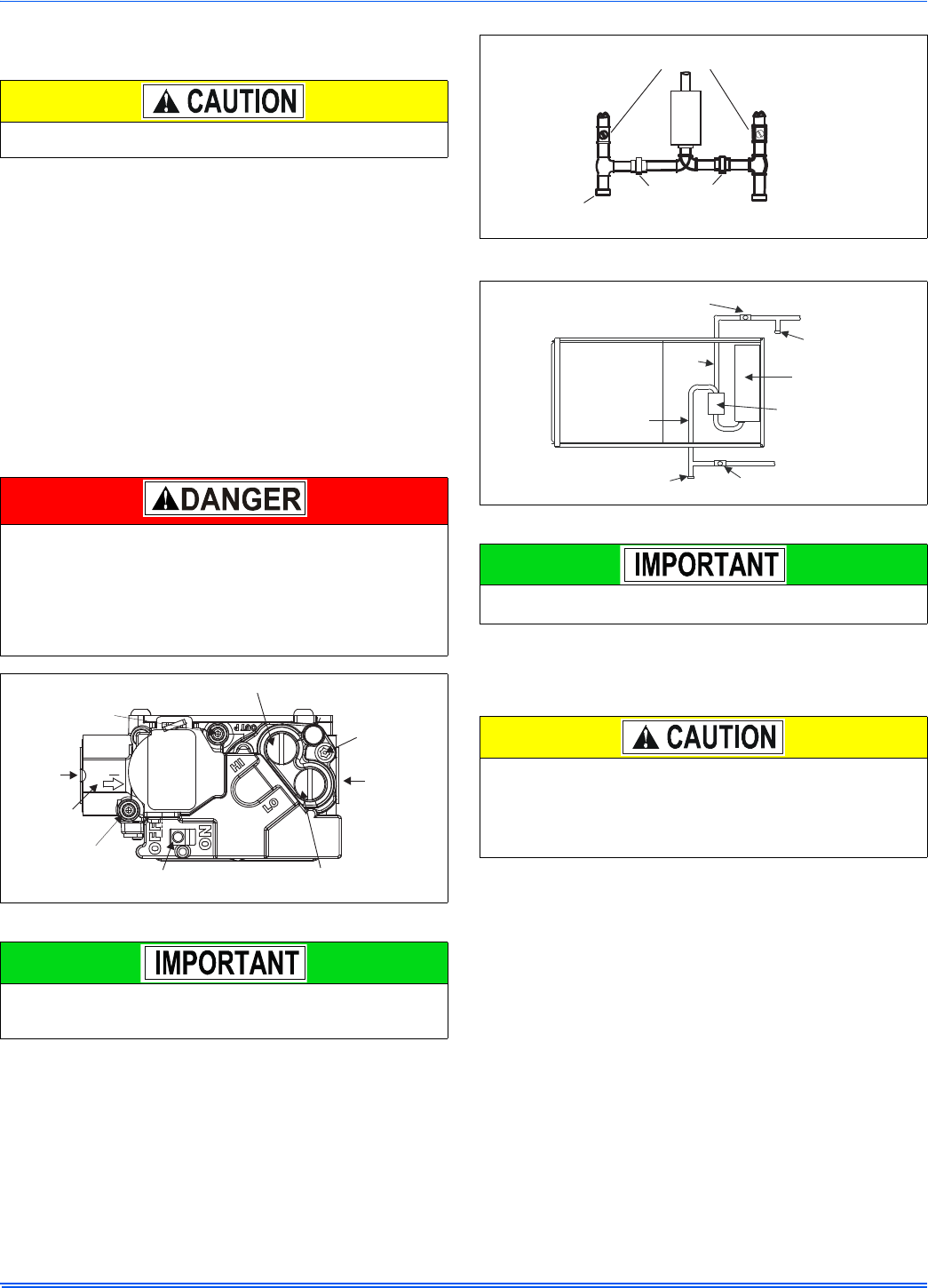
FIGURE 14: Gas Valve
Plan your gas supply before determining the correct gas pipe entry.
Use 90-degree service elbow(s), or short nipples and conventional
90-degree elbow(s) to enter through the cabinet access holes.
INLET
WRENCH
BOSS
INLET
PRESSURE
PORT
ON OFF
SWITCH
LOW STAGE REGULATOR
ADJUSTMENT
OUTLET
OUTLET
PRESSURE
PORT
VENT
PORT
HIGH STAGE REGULATOR
ADJUSTMENT
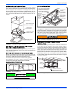
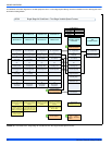
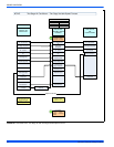
FIGURE 15: Upflow/Downflow Gas Piping
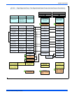
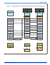
FIGURE 16: Horizontal Gas Piping
An accessible manual shutoff valve must be installed upstream of
the furnace gas controls and within 6 feet (1.8 m) of the furnace.
The gas valve body is a very thin casting that cannot take any
external pressure. Never apply a pipe wrench to the body of the gas
valve when installing piping. A wrench must be placed on the octa-
gon hub located on the gas inlet side of the valve. Placing a wrench
to the body of the gas valve will damage the valve causing improper
operation and/or the valve to leak.
External Manual
Shutoff Valve
To Gas
Supply
To Gas
Supply
Grounded Joint Union
may be Installed
Inside or Outside Unit.
Drip Leg
Manual
Shut-off
Valve
Gas
Pipe
Gas
Pipe
Drip
Leg
Manual
Shut-off Valve
Gas Valve
Gas Burners
Drip
Leg