


364985-XIM-B-0508
8 Johnson Controls Unitary Products
COMPRESSORS
Units are shipped with compressor mountings factory-
adjusted and ready for operation.
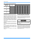
Units with scroll compressors have a shipping bracket
which must be removed after the unit is set in place.
See Figure 2.
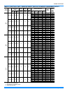
FILTERS
One-inch or two-inch filters can be supplied with each
unit. Filters must always be installed ahead of the
evaporator coil and must be kept clean or replaced with
same size and type. Dirty filters will reduce the capacity
of the unit and will result in frosted coils or safety shut-
down. Minimum filter area and required sizes are
shown in Physical Data Table 7.
SERVICE ACCESS
The following removable panels provide access to all
serviceable components:
• Compressor compartment
• Electric Heat compartment
• Blower compartment
• Main control box
• Filter compartment
Refer to the Dimensions and Clearances shown in Fig-
ures 7 and 11 for location of these access panels.
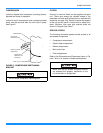
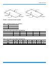
FIGURE 2 - COMPRESSOR RESTRAINING
BRACKET
Do not loosen compressor mounting bolts.
WIRE TIE (CUT AND REMOVE)
MOUNTING
BRACKET TOP
(REMOVE)
MOUNTING
BRACKET BASE
REMOVE THESE
SCREWS (2)
COMPRESSOR
Make sure that all screws and panel latches
are replaced and properly positioned on the
unit to maintain an airtight seal.